
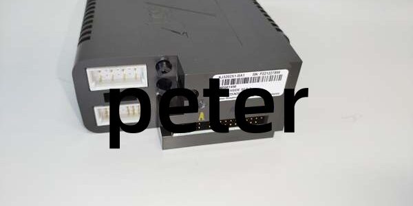
Product Core Brief
- Model: VE4032S1T2B1 (cross PN KJ3202X1-BA1, 12P2536X042)
- Brand: Emerson DeltaV
- Series: M-Series Traditional Rack I/O Redundant Hardware
- Core Function: 8-channel redundant high-side 24VDC discrete output card to drive solenoid valves, motor relays and alarm indicators for high-availability control loops
- Product Type: Plug-in rack-mounted redundant DO I/O module, mates with standard screw termination base
- Key Specs: 1A per channel continuous | 3A total field limit | per-channel foldback protection | bumpless dual-card auto failover
- Note: New original surplus stock; only fits M-series 8-slot I/O carriers, incompatible with S-series rack infrastructure
Key Technical Specifications
| Parameter | Value |
|---|---|
| Channel Layout | 8 independent high-side sourcing discrete output channels |
| Nominal Field Voltage | 24 VDC ±15% field supply |
| Per-Channel Continuous Load | 1 A resistive steady-state |
| Aggregate Field Current Limit | 3 A total across all 8 output channels |
| Fault Protection Hardware | Per-channel short-circuit foldback limiting, auto-reset post fault clearance |
| Redundancy Operation | Dual-card hot standby with zero-latency bumpless failover on primary fault |
| Backplane Communication | DeltaV LocalBus, 12VDC rack backplane, 150mA module power draw |
| Hot-Swap Capability | Safe live insertion/removal on energized safe-zone rack slots |
| Operating Temperature | -40°C to +70°C operational; -40°C to +85°C storage |
| Environmental Rating | ISA S71.04 G3 corrosive gas resistant, full PCB conformal coating |
| Physical Dimensions | 107 mm W × 41 mm H × 105 mm D; net weight 0.30 kg |
| Vibration & Shock | 1mm pp (2–13.2Hz); 0.7g constant (13.2–150Hz); 10g half-sine 11ms shock |
| Hazardous Certifications | FM Class I Div2, ATEX Ex ec IIC Gc (Zone 2 cabinet mounting only) |
| Compatibility Restriction | No mechanical or bus signal compatibility with DeltaV S-series I/O carriers |
Product Introduction
This rack-mounted redundant discrete output hardware switches 24VDC power to field actuators within critical DeltaV process control racks. Per-channel current limiting isolates wiring shorts to a single output without disabling all 8 control points on the carrier backplane.Dual-card standby redundancy eliminates single-point actuation failure risk for anti-surge valve and pump interlock circuits. High-side sourcing topology eliminates ground leakage currents that trigger unintended valve chatter on long multi-conductor field cables routed near motor control centers.
QA & Testing SOP
- Incoming Inspection: Match serial numbers against OEM factory batch logs; inspect gold LocalBus edge connectors for oxidation and plastic housing for cracking. Reject units with peeling PCB conformal coating or bent pin headers.
- Live Functional Testing: Install on matching M-series carrier, supply rack 12VDC LocalBus power via Fluke 115 multimeter. Toggle each channel 500 times with 1A resistive loads to validate consistent state reporting to DeltaV HMI.
- Short-Circuit & Redundancy Stress Test: Force field-side shorts on each channel to verify foldback lockout engages without PCB overheating; pair two identical units to confirm seamless bumpless failover during primary power cut.
- Firmware Logging: Capture factory firmware revision through DeltaV Diagnostic Console and save timestamped screenshots linked to the unit serial number for full traceability.
- Final QC & Packaging: Blow PCB surfaces with dry nitrogen to remove industrial dust; seal unit in static-shield bag with printed test report containing 24-hour continuous full-load runtime stability data.
Installation Pitfalls & Guide
❗ ESD Component Failure Risk: Ungrounded contact with backplane pins destroys output driver MOSFET ICs; component replacement labor exceeds $2,200. Always attach a grounded anti-static wrist strap to cabinet safety ground before handling the module.❗ Cross-Series Carrier Mismatch: This hardware only seats on M-series racks. Forced insertion into S-series carriers bends backplane gold pins and disables full rack LocalBus communication.❗ Zone 0/1 Hazardous Area Misuse: The card holds only Div2 safety certification. Deploying it in Zone 0 or 1 flammable gas cabinets voids all safety approvals and creates ignition hazards.❗ Mismatched Redundant Card Revisions: Pairing different firmware revisions for standby redundancy creates delayed failover and intermittent actuator chatter during primary card fault events. Match identical hardware rev levels for redundant deployments.❗ Unsuppressed Inductive Loads: Solenoid and relay coils without parallel flyback diodes generate reverse voltage transients that permanently punch through onboard switching transistors and disable individual channels.
4-Step Replacement Guide
- Pre-install: Activate interlock bypass logic on the DeltaV workstation for all 8 associated field control loops; photograph terminal block field wiring layout for rebuild reference. Hot-swap is permitted in safe zone cabinets; leave the standby redundant card powered to maintain actuation coverage during swap.
- Removal: Release the card’s front retention latch, pull the unit straight outward horizontally to avoid bending backplane edge pins.
- Install: Align the new module’s gold backplane connector with the carrier slot, push fully until the retention latch clicks into locked seated position.
- Power-on Test: Clear all loop bypasses; toggle each field solenoid repeatedly, simulate channel short conditions to verify single-channel fault isolation, and trigger primary card power loss to validate seamless redundant failover with zero valve state dropout.
FAQ
Q: Can multiple solenoid coils wire in parallel on a single channel?A: Yes, provided combined total steady-state current does not exceed the 1A per-channel continuous rating; exceeding this threshold triggers persistent foldback short-circuit lockout on the affected output.Q: Does hot-swapping this unit disrupt other I/O modules on the same carrier rack?A: The M-series carrier includes buffered hot-swap circuitry; removing or inserting the unit while rack power stays energized will not interrupt signal processing for other installed I/O cards. In redundant rack layouts, the standby card maintains full actuator control during primary card replacement.Q: What physical limitation blocks use with S-series DeltaV racks?A: M-series and S-series carriers use incompatible backplane pinout geometries and LocalBus signaling timings; forced installation permanently damages the carrier’s backplane connector pins.Q: What hardware fault patterns signal a failed unit?A: One or multiple channels fail to energize field loads, constant short-circuit fault flags on intact wiring, full LocalBus communication timeout on the carrier rack, missing front-panel channel status LED indicators, or failed redundant failover during primary card power loss.Q: What warranty coverage applies to new surplus stock?A: A 12-month limited warranty covers factory PCB and assembly defects. Damage from ESD mishandling, unsuppressed inductive load kickback, field-side overvoltage, mismatched redundant firmware revisions, or deployment in unapproved hazardous zones is excluded from coverage.Q: Can non-redundant standard DO cards substitute this unit for redundant rack setups?A: No, standard single-mode DO hardware lacks the dual-card cross-check and auto-failover logic built into this unit, preventing valid redundant I/O configuration within DeltaV control logic.




