
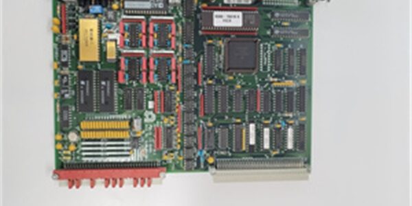
Product Core Brief
- Model: 0100-20100
- Brand: Applied Materials (AMAT)
- Series: Centura Wafer Processing Platform Spare RF Hardware Line
- Core Function: Matches variable plasma chamber impedance to 50Ω RF generator output at 13.56MHz to stabilize etch and thin-film deposition process plasma
- Product Type: Air-cooled automatic RF impedance matching network assembly
- Key Specs: 13.56MHz operating frequency | 500W continuous RF power rating | Closed-loop servo impedance tuning
- Note: New Original OEM spare; matching AMAT RF power generators sold separately
Key Technical Specifications
- Operating Frequency: Fixed 13.56 MHz industrial RF plasma band
- Max Continuous RF Input Power: 500 W
- System Impedance Target: 50 Ω nominal generator side
- Tuning Range: Capacitive servo covers 5Ω to 150Ω plasma load impedance
- Cooling Method: Forced air convection via integrated low-noise cooling fan
- Control Interface: RS232 serial + analog 0–10V setpoint/feedback signal connectors
- Process Compatibility: Centura dielectric etch, PVD, CVD thin film deposition chambers
- Input RF Connector: 7/16 DIN high-power coaxial RF port
- Mechanical Enclosure: Aluminum alloy sealed cabinet, IP30 cleanroom rating
- Operating Ambient: 18°C to 26°C cleanroom environment; 30–70% non-condensing humidity
- Safety Standards: SEMI S2, CE industrial EMC compliance
- Unit Weight: 4.2 kg
- Dimensions: 220 mm W × 310 mm H × 165 mm D
Product Introduction
This RF match is a critical subassembly for AMAT Centura wafer processing tools. It eliminates plasma impedance drift during batch wafer runs by auto-adjusting internal variable capacitors to maintain stable RF power transfer into vacuum process chambers.
Integrated closed-loop servo tuning delivers sub-100ms impedance correction speed to prevent process drift, wafer thickness variation, and generator over-trip faults common in semiconductor manufacturing. Air-cooled construction removes liquid cooling plumbing requirements for simplified chamber maintenance.
QA & Testing SOP (Transparency Building)
- Incoming Inspection: Cross-reference AMAT OEM serial database to validate genuine cleanroom-grade hardware; inspect RF coaxial ports for pin damage, cooling fan assembly for blade warping, and enclosure sealing gaskets for cracking.
- Live Testing: Pair the unit with calibrated 13.56MHz RF generator and variable dummy plasma load; supply facility 24VDC control power; run 24-hour cyclic 80% power load test, logging tuning response time and reflected power levels hourly.
- Electrical RF Testing: Network analyzer sweep from 10MHz to 15MHz; pass threshold <0.5% reflected power at target 13.56MHz frequency.
- Firmware/Config Backup: Record servo tuning PID parameter set stored on onboard flash memory; photograph RS232 and analog control wiring pinout for replacement matching.
- Final QC & Packaging: Purge internal cavity with dry nitrogen for cleanroom cleanliness; seal inside double anti-static vacuum bag; attach printed test tag with serial trace and reflected power test data.
Installation Pitfalls & Guide (Engineer to Engineer)
❗ RF Generator Frequency Mismatch: This unit is locked to 13.56MHz only. Pairing with 2MHz or 400kHz bias generators creates uncorrectable high reflected power and immediate generator shutdown.❗ Improper Coaxial Torque Torque: Under-tightened 7/16 DIN RF connectors introduce impedance discontinuities; over-torquing cracks internal center pin insulators, causing permanent RF leakage damage. Follow OEM 12 N·m torque spec strictly.❗ Unfiltered Cleanroom Air Supply: Dust particles pulled into the match via cooling fan coat variable capacitor plates, leading to slow tuning drift after 2–3 months of continuous production. Install OEM inline particle filter at cooling intake.❗ Parallel Low-Voltage Control Cabling Routing: Running RS232 analog control wires parallel to high-power RF coax induces signal noise, triggering false out-of-impedance process interlock faults mid-wafer batch. Separate cable trays by minimum 15cm gap.❗ Unmitigated RF & ESD Exposure: Un-grounded service technicians face high-frequency RF burn risk during live chamber troubleshooting; wear RF-rated anti-static wristbands and insulated service gloves before opening enclosure panels.
4-Step Replacement Guide
- Pre-install: Full tool RF generator and chamber facility power shutdown; photograph RF coax routing, analog control pinouts, and cooling air filter mounting position for exact configuration replication.
- Removal: Disconnect high-power 7/16 DIN RF cable; unplug RS232 and analog control terminal harness; release four cabinet mounting fasteners and extract the assembly from chamber rack.
- Install: Secure new unit to rack with OEM torque values; re-seat RF coax to specified 12 N·m torque; reconnect all control wiring matching photographed pin assignments; install new OEM air intake particle filter.
- Power-on Test: Restore facility control power and RF generator supply; run auto-tune calibration routine; verify reflected power remains below 0.5% across full process impedance range before releasing wafer production batches.
FAQ (Frequently Asked Questions)
Q: Can this assembly run continuous 500W full-power operation for 24-hour production shifts?A: Yes, under proper filtered cooling air flow and 20°C nominal cleanroom ambient. Sustained 500W operation above 26°C triggers internal thermal interlock shutdowns.Q: Does this RF match support hot-swap while the Centura tool remains powered?A: No. Live RF line disconnection creates hazardous high-frequency voltage transients, damages generator internal power semiconductors, and poses RF burn safety hazards to staff. Full facility power lockout/tagout is mandatory.Q: What causes persistent high reflected power faults after swap-in of a new unit?A: Most common root causes are mis-torqued RF coax connectors, missing air intake filters, or chamber plasma showerhead deposition buildup shifting baseline load impedance outside the tuning window.Q: Is third-party generic RF matching hardware drop-in interchangeable with this OEM unit?A: No. Third-party matches lack AMAT proprietary servo tuning PID firmware optimized for Centura chamber plasma profiles, leading to uncorrectable wafer process thickness non-uniformity.Q: How often does the internal variable capacitor assembly require preventive maintenance?A: OEM service interval is 12 months of continuous production, dependent on cleanroom air particle count. Facilities with unfiltered cooling reduce service life to 6 months.Q: Can this unit integrate with non-AMAT semiconductor processing chambers?A: Physically compatible via standard 50Ω RF ports, but proprietary analog interlock and serial communication protocols only natively interface with AMAT Centura tool control systems.Q: What warranty coverage applies to surplus OEM spare units?A: Standard 12-month functional warranty covers servo tuning circuitry and RF capacitor manufacturing defects; damage from over-torqued RF connectors, unfiltered cooling dust ingress, or live RF service mishandling is fully excluded from coverage.




