
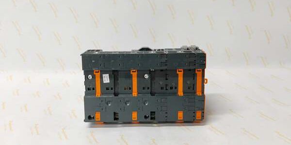
Product Core Brief
- Model: 3IF661.9
- Brand: B&R Industrial Automation
- Series: 2005 Rack CPU Expansion Interface Line
- Core Function: Adds galvanically isolated PROFIBUS DP slave RS485 bus communication to 2005-series rack CPUs for third-party drive, sensor, and HMI fieldbus integration
- Product Type: Backplane plug-in fieldbus communication interface module
- Key Specs: Isolated RS485 PROFIBUS DP slave | D-Sub 9 connector | 12 Mbps maximum bus transmission rate | Per-channel diagnostic LEDs
- Note: New Original inventory; compatible 2005 CPU base racks sold separately
Key Technical Specifications
- Supported Protocol: PROFIBUS DP Slave, RS485 physical layer
- Maximum Bus Speed: 12 Mbps adjustable via module DIP switches
- Electrical Isolation: 500 Vₑff galvanic isolation between backplane logic and PROFIBUS field wiring
- External Connector: Standard 9-pin D-Sub male port for PROFIBUS cable termination
- Onboard Indicators: RUN status LED, BUS ERROR fault LED for real-time fieldbus diagnostics
- Power Draw: 0.8 W nominal backplane power consumption
- Mechanical Dimensions: 18 mm width × 60 mm height × 130 mm depth; unit weight 0.1 kg
- Mount Format: Single-width plug-in slice for 2005 rack backplane slots
- Protection Class: IP20 for cabinet-only indoor installation
- Operating Temperature: Horizontal rack -25°C to +60°C; vertical rack -25°C to +50°C
- Storage Temperature: -40°C to +85°C; 5%–95% non-condensing relative humidity
- Certifications: CE, UL cULus, EAC industrial compliance
- Compatible Hardware: All 2005-series rack CPU controllers; does not fit X20 or APC rack backplanes
Product Introduction
This narrow fieldbus slice expands legacy 2005 rack CPUs with PROFIBUS DP slave connectivity to link external third-party drives, weighing modules, and remote operator panels without separate gateway hardware. Built-in galvanic isolation eliminates ground-loop communication failures between cabinet and field device wiring.
Adjustable DIP switch bus speed settings match mixed-length PROFIBUS cable runs, while dedicated fault LEDs cut on-site troubleshooting time by flagging shorted bus lines or duplicate slave address conflicts without software access.
QA & Testing SOP (Transparency Building)
- Incoming Inspection: Cross-reference OEM serial logs to validate genuine hardware; inspect D-Sub connector pins for bending, backplane gold edge contacts for oxidation, and DIP switch bank for mechanical damage.
- Live Testing: Seat the slice into a calibrated 2005 CPU rack powered by a Fluke 115 stabilized 24VDC supply; connect PROFIBUS DP master simulator to D-Sub port; run 24-hour cyclic read/write test at 1.5 Mbps and 12 Mbps bus speeds, logging communication error counts hourly.
- Electrical Testing: 500V Megger insulation test between PROFIBUS signal terminals and backplane ground; pass threshold set to >10MΩ isolation resistance.
- Firmware/Config Backup: Record factory default DIP switch speed settings via Automation Studio; photograph D-Sub pinout layout for replacement wiring matching.
- Final QC & Packaging: Wipe PCB surface with ESD-safe isopropyl alcohol; seal in conductive anti-static shielding bag; attach printed test tag listing serial trace and 24-hour error-free communication metrics.
Installation Pitfalls & Guide (Engineer to Engineer)
❗ Rack Backplane Mismatch: This slice only inserts into 2005-series rack slots. Forced installation into X20 or APC backplanes bends edge connector pins and permanently damages internal bus transceivers.❗ Misconfigured DIP Switch Bus Speed: Setting 12 Mbps on cable runs longer than 100 meters generates constant BUS ERROR LED faults and cyclic communication timeouts. Match switch speed to total field cable length per PROFIBUS standard limits.❗ Missing PROFIBUS Line Terminator: The farthest slave device on the DP bus chain requires a 120Ω bus terminator resistor; omitted termination creates signal reflection that drops packet throughput by 70% at high speeds.❗ Parallel Power Cable Routing: Running PROFIBUS RS485 cabling alongside heavy AC motor power wiring induces EMI noise, triggering intermittent BUS ERROR flashes during machine acceleration cycles.❗ Unmitigated ESD Exposure: Low-humidity static discharges damage isolated RS485 transceiver circuitry; wear grounded anti-static wristbands before plugging the slice onto the rack backplane.
4-Step Replacement Guide
- Pre-install: Full rack power shutdown; photograph existing slice DIP switch speed settings, D-Sub PROFIBUS cable pinout, and backplane slot position for exact configuration replication.
- Removal: Depress orange rack locking latch; slide the slice straight upward off the backplane; disconnect D-Sub fieldbus wiring.
- Install: Seat the new unit flush into the empty 2005 rack slot until the latch clicks fully; set DIP switches to match documented bus speed parameters; reattach PROFIBUS cable to D-Sub port.
- Power-on Test: Restore 24VDC rack supply; verify steady RUN LED, zero BUS ERROR flashes, and complete cyclic data exchange with the PROFIBUS master simulator before production operation.
FAQ (Frequently Asked Questions)
Q: Does this module operate as a PROFIBUS DP master device?A: No. Hardware logic is locked exclusively to DP slave mode. Master communication requires separate 3IF660-series master interface slices for the same 2005 rack platform.Q: Can this slice hot-swap while the 2005 rack remains powered?A: No. Removing the slice live breaks the rack’s internal backplane bus, halts all CPU logic execution, and risks permanent damage to backplane transceiver chips. Full rack power shutdown is mandatory.Q: What maximum cable length works reliably at 12 Mbps bus speed?A: Only up to 100 meters of shielded PROFIBUS cable. Extending runs past this distance forces speed reduction to 1.5 Mbps for stable data exchange.Q: Is third-party unshielded cable compatible with the D-Sub port?A: Physically compatible, but unshielded wiring lacks required EMC noise suppression. Field data shows 6x higher cyclic communication fault rates with non-certified PROFIBUS cabling.Q: How many external PROFIBUS slave devices can the host CPU address through one of these slices?A: Up to 31 unique slave node addresses per DP bus segment, matching standard PROFIBUS DP wiring limits without repeaters.Q: Will this module communicate with modern ACOPOS P3 servo drives over PROFIBUS DP?A: Yes, but drive firmware must enable DP slave mode; newer drive generations prioritize POWERLINK native communication for motion synchronization.Q: What warranty coverage applies to surplus stock of the slice?A: Standard 12-month functional warranty covers transceiver and isolation circuit manufacturing defects; damage from ESD mishandling, missing bus terminators, or parallel power cable EMI interference faults is fully excluded from coverage.





