
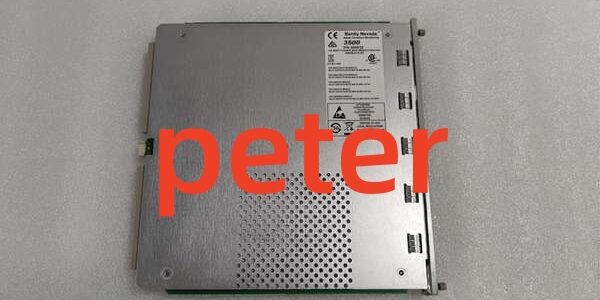
Product Core Brief
- Model: 3500/22-01-01-00 (3500/22M standard TDI, front assembly PN 138607-01)
- Brand: Bently Nevada (Baker Hughes)
- Series: 3500 Machinery Protection TSI Rack System
- Core Function: Mandatory Slot1 rack master that aggregates all monitor data, stores post-fault vibration waveforms, and bridges rack telemetry to System1 and plant DCS
- Product Type: Single-slot hot-swappable transient data interface (TDI)
- Key Specs: 10/100BASE-TX Ethernet + USB-B front ports | 64kHz max waveform sampling | 10.2W maximum power draw
- Note: Legacy active production unit, factory-new and refurbished surplus stock available; superseded by 288055-01 variant with expanded flash memory.
Key Technical Specifications
- Mandatory mounting position: Rack Slot 1, adjacent to redundant rack power supplies
- Power supply: 24VDC rack backplane bus, continuous power draw capped at 10.2W
- Front panel I/O: Autosensing 10/100 RJ45 Ethernet port, USB-B local configuration port, security key lock, four multi-state status LEDs
- Transient sampling rate: Up to 64kHz for high-resolution vibration waveform capture
- Local storage: Non-volatile onboard flash for timestamped fault snapshots; smaller capacity than the newer 288055-01 assembly
- Galvanic isolation: 1500VAC isolation barrier separating front communication ports and internal rack backplane logic
- Operating temperature: -30°C to +65°C standard operating range; conformal coated version rated -40°C to +85°C
- Supported industrial protocols: EGD, Modbus TCP, SNTP time synchronization, proprietary 3500 rack backplane bus
- Physical dimensions: Standard single 3500 rack slot form factor, unit weight 0.82kg
- Compliance certifications: API 670, CE EMC, UL Class I Div 2, ATEX Zone 2 hazardous cabinet rating
- Critical safety design: All monitor hardwired alarm/trip relays operate independent of this unit; module failure cannot block machinery emergency shutdown interlocks
Product Introduction
This rack master TDI unifies legacy RIM backplane control and transient waveform capture hardware into one single-slot component for all M-series monitor equipped 3500 racks. It continuously polls vibration, overspeed, and temperature cards to push steady-state measurement data to DCS historians.Its primary field limitation is constrained onboard flash storage. High-channel compressor and turbine racks rapidly fill memory and overwrite older fault waveforms, eliminating critical post-trip diagnostic data without routine manual waveform exports.
QA & Testing SOP (Transparency Building)
- Incoming Inspection: Cross-reference serial numbers against OEM production databases to reject counterfeit hardware. Complete physical audit of PCB traces, front port pins, key lock mechanism, and LED arrays; capture timestamped photos of all cosmetic defects.
- Live Power-On Testing: Install the unit in a calibrated test 3500 rack fed by a Fluke 115 24VDC supply. Execute a continuous 24-hour load test with full rack channel simulation to validate consistent power draw and stable Ethernet link operation.
- Electrical Isolation Testing: Use a megohmmeter to verify insulation resistance >10MΩ between Ethernet signal conductors and rack protective ground; confirm zero leakage current across all isolation boundaries.
- Firmware & Config Backup: Flash the latest OEM compatible firmware revision, log exact version numbers, and archive a blank rack configuration file to offline storage. Record baseline LED behavior during full rack backplane scan cycles for failure comparison.
- Final QC & Packaging: Trigger a simulated Alert alarm to confirm flash memory properly writes waveform snapshots. Place the unit in anti-static foam, attach serialized QC test tag with test timestamp, and seal inside ESD shielding packaging for shipment.
Installation Pitfalls & Guide (Engineer to Engineer)
❗ Firmware Rev Mismatch Risk: Mismatched firmware versions across rack monitor cards trigger permanent CONFIG fault LEDs and halt backplane data polling. Export the full rack firmware stack before swapping the unit; never deploy mixed revision firmware sets.❗ Flash Storage Overwrite Risk: Dense multi-bearing machinery racks exhaust limited onboard flash memory; historical fault waveforms auto-delete to make space for new trigger events, erasing root-cause diagnostic records.❗ Dual-End Ground Loop Violation Risk: Grounding Ethernet cable shielding at both the TSI rack and plant network switch creates circulating ground loop current that corrupts EGD data frames, causing intermittent full rack tag dropout during VFD startup transients.❗ ESD Damage Risk: Ungrounded field tools discharge static through front USB/Ethernet ports, destroying internal CPU circuits; OEM PCB repair costs exceed $1,700 for legacy hardware.❗ Cross-Variant Swap Failure Risk: Direct replacement with the updated 288055-01 assembly requires a full rack firmware upgrade; un-upgraded racks generate persistent backplane handshake faults post-installation.
4-Step Replacement Guide
- Pre-install: Secure ESD wrist strap, photograph front LED status of the existing unit, export complete rack configuration, and record all active firmware revisions. Document total rack channel count to plan for flash storage limits.
- Removal: Rotate front security key to PROGRAM mode, pull extraction levers to disengage backplane pins, slide the unit straight out of Slot 1 without twisting the PCB edge connector.
- Install: Align replacement unit backplane pins with rack bus, slide fully into Slot 1, squeeze extraction levers to lock contact pins, rotate key lock to RUN mode to lock configuration edits.
- Power-on Test: Restore rack power, upload saved rack configuration file, trigger a test Alert alarm on a vibration channel to validate waveform storage and continuous DCS tag readback. Review flash memory utilization to mitigate data overwrite risks.
FAQ (Frequently Asked Questions)
Q: Does this unit support hot-swap operation with the rack energized?A: Yes, the hardware is rated for live hot-swap without full rack power loss. All monitor safety relay trip circuits remain active during removal and replacement, so machinery emergency shutdown logic stays fully functional.
Q: Can this assembly be directly replaced with the newer 288055-01 TDI variant?A: Partial hardware compatibility exists, but cross-installation without a full rack firmware upgrade generates constant backplane communication faults. Unified rack firmware matching the replacement hardware’s OEM release is mandatory for bumpless swap.
Q: What warranty coverage applies to refurbished surplus inventory?A: Refurbished stock carries a 12-month functional warranty covering PCB communication and storage circuits; cosmetic surface wear and scratches are excluded from claims. Factory-new OEM units ship with a full 36-month manufacturer warranty.
Q: Will power cycling the rack erase stored transient fault waveforms on the device?A: No. All waveform snapshots save to non-volatile onboard flash memory; power cycles do not delete historical fault event data, though high channel counts risk automatic overwrite of older records.
Q: Is an optional channel disk required to capture dynamic vibration waveforms?A: Static steady-state trending operates without the disk accessory. High-speed dynamic waveform capture for fault diagnostics requires the OEM channel enabling disk installed on the PCB.
Q: Can I operate the module without connecting the front Ethernet port to a plant control LAN?A: Yes. Local USB-B connection to a field laptop supports all configuration upload/download and waveform export functions without active network wiring. Real-time DCS trending will remain disabled until Ethernet connectivity is restored.
Q: Does this unit control machinery safety shutdown protection logic?A: It does not. All overspeed, vibration, and temperature relay trip circuits run independently on each monitor card. Internal faults on the unit cannot disable hardwired emergency shutdown interlock functionality.





