
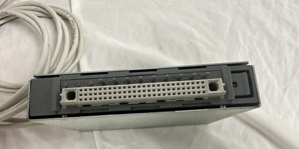
Component Snapshot At-a-Glance
- Model: T8153; harsh environment coated variant T8153C
- Alt. P/N: No interchangeable substitute; exclusively mates with T8151B / T8151CI communications interface modules
- Product Series: ICS Triplex Trusted 8000 TMR Safety Instrumented System
- Hardware Type: Rear-chassis clip-on communications breakout adapter
- Key Feature: Exposes all internal T8151B serial/Ethernet ports to field wiring terminals; dual RJ45 Ethernet, 4×RS485 multi-drop, full/partial RS232 banks; quick-release SK1 rear connector
- Primary Field Use: Physical termination point for Modbus TCP, Modbus RTU, IRIG-B time sync, HMI/historian cabling off T8151B CI cards in SIL3 SIS racks.
Hard-Numbers: Technical Specifications
- Protocol Support: Mirrors T8151B native protocols: Modbus TCP, Modbus RTU Master/Slave, IRIG-B time sync, Trusted peer-to-peer
- Port Count: SK1 78+2 pin rear chassis connector; 2×RJ45 10/100 Ethernet; 4 independent RS422/485 multi-drop banks; Bank1 full RS232 (TX/RX/RTS/CTS/DTR/DSR/DCD); Bank2 partial RS232 (TX/RX/RTS/CTS); screw terminal field wiring banks
- Baud/Data Rate: Serial baud range 300–115200 bps; Ethernet auto 10/100 full duplex; IRIG-B 1PPS timestamp resolution
- Operating Temperature: -5°C to +60°C standard T8153; T8153C rated -40°C to +70°C salt fog/oil mist enclosures
- Isolation Rating: 1500VAC opto-isolation per serial/Ethernet port bank against field wiring transients
- Power Draw: Passive breakout, draws no independent power; power routed directly from paired T8151B backplane supply
- RS485 Capacity: Each multi-drop bank supports up to 32 Modbus field devices; built-in line bias resistors jumper-selectable
- Physical: Aluminum sealed enclosure; weight 418g; rear chassis clip mount with spring release latch; IP20 cabinet-only rating
- Safety Rating: CE, UL, ATEX Zone 2 / Class I Div 2 non-incendive approval, SIL3 compatible auxiliary comm hardware
The Real-World Problem It Solves
T8151B CI modules have buried rear internal port pins inaccessible without full chassis disassembly. Direct soldering to rear pins creates fragile vibration-prone connections that drop Modbus links mid-process run. Separate external terminal blocks add extra DIN rail footprint and splice points that introduce ground loop noise skewing SOE timestamps.
- Where you’ll typically find it:
- Refinery hydrocracker SIS chassis rear, terminating Modbus RTU field transmitters and plant DCS historian Ethernet links
- Combined-cycle power plant burner management safety racks handling IRIG-B time sync and HMI operator panel serial connections
- Offshore platform hazardous zone ESD control racks using T8153C coated hardware to block salt fog PCB corrosionClip-on rear breakout design eliminates chassis disassembly for comm wiring changes, integrated port banks consolidate all external comm terminations in one sealed unit, and built-in port isolation cuts ground-loop induced Modbus frame corruption.
Hardware Architecture & Under-the-Hood Logic
This is a passive signal breakout unit with no onboard processor or logic; all communication stack processing lives entirely on the paired CI card. It only routes isolated signal paths from the rear internal connector to external field wiring terminals.
- Spring-locked SK1 high-density DIN41612 connector fully mates to the rear port header of a single communications module; release button enables quick removal without unbolting chassis hardware.
- Internal PCB traces split the ’s four serial channels into dedicated isolated port banks; Bank1/Bank2 multiplex RS232 or RS485 via internal configuration jumpers (cannot run both modes on same bank simultaneously).
- Dual isolated RJ45 Ethernet ports hardwired to ’s primary/secondary redundant Ethernet transceivers, supporting automatic network failover without reconfiguring field cabling.
- Each RS485 bank includes jumper-selectable 120Ω line termination and bias resistors to eliminate multi-drop bus reflection and floating signal faults on long field cables.
- Full RS232 bank exposes all modem control handshaking lines for engineering laptop direct uploads; partial RS232 bank reserved for fixed low-speed auxiliary serial devices.
- T8153C conformal coated variant seals PCB traces, port isolation transformers and jumper banks to resist condensation, oil mist and salt fog in unconditioned process control rooms.
Field Service Pitfalls: What Rookies Get Wrong
Dual-End Grounding Serial/Ethernet Shield Cables
New techs ground shield braid at both T8153 terminal banks and remote DCS/historian switch cabinets. Ground loop AC noise corrupts Modbus RTU frames and skews millisecond IRIG-B SOE timestamps during VFD compressor cycling.
- Field Rule: Terminate all communication cable shield only at the Trusted rack chassis ground bar; tape and fully isolate shield conductors at all remote network/field device enclosures.
Mixing and RS485 Modes On The Same Port Bank
Techs wire RS485 multi-drop transmitters to a bank configured for handshaking without adjusting internal jumpers. Signal level conflict creates permanent port lockout on the paired , triggering persistent comm fault alarms.
- Quick Fix: Set bank jumpers to match the field device signal type before cabling; label each port bank on the T8153 enclosure to prevent future misconfiguration.
Forgetting 120Ω Termination Resistors On Long Trunks
Rookies skip bus termination for multi-drop Modbus runs over 300m. Signal reflection causes intermittent tag timeouts and lost safety alarm data during plant load transients.
- Field Rule: Enable 120Ω termination jumpers at the furthest two endpoints of every trunk; disable termination on all intermediate field transmitters.
Commercial Availability & Pricing Note
Please note: The listed price is for reference only and is not binding. Final pricing and terms are subject to negotiation based on current market conditions and availability.





