Component Snapshot At-a-Glance
- Model: METSO D201471, part designation DOI4RO, Revision 05
- Alt. P/N: D201472 (8DI solid-state only variant); D201473 (8RO relay output only variant); A413188 (8ch analog input, unrelated function)
- Product Series: Metso DNA RT Node AP31 remote I/O personality module family, mates with base unit D200137
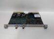
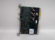
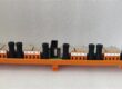
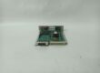
- Hardware Type: Horizontal plug-in personality PCB, front screw terminal block for field 24V wiring, individual channel status LEDs, gold rear edge connector to RT node backplane
- Key Feature: 4 opto-isolated 24VDC digital inputs + 4 form-C relay dry contact outputs, per-channel TVS surge suppression, hot-swappable on AP31 RT node racks
- Primary Field Use: Capture breaker, valve, motor auxiliary contact status; drive annunciator alarm lights, solenoid interlock relays on remote DNA RT I/O nodes.
Hard-Numbers: Technical Specifications
- Protocol Support: Proprietary DNA RT node internal parallel backplane bus, no external fieldbus ports on personality card
- Port Count: 4 x 24VDC opto-isolated DI terminals; 4 x Form-C relay dry contact output terminals
- Baud/Data Rate: RT node fixed 100ms full channel scan refresh cycle
- Operating Temperature: 0°C to +55°C cabinet operational; -40°C to +85°C storage
- Isolation Rating: 1500Vrms opto-isolation between DI field wiring and RT node internal logic
- Power Draw: 2.7W total module load at nominal 24VDC RT node supply
- Main Input Power: 20–30VDC station cabinet battery, nominal 24VDC backplane feed
- DI Signal Threshold: Logic 1 ≥18VDC, Logic 0 ≤6VDC wet contact inputs
- Relay Contact Rating: 250VAC / 30VDC, 3A resistive max per Form-C output
- EMC Compliance: IEC 61000-6-2 industrial surge, VFD noise and cabinet vibration immunity
- PCB Treatment: Full acrylic anti-moisture conformal coating for pulp mill / mineral processing dusty cabinets
- Physical Weight: 0.38kg single personality slot form factor
The Real-World Problem It Solves
Stacking separate D201472 DI-only and D201473 relay output personality cards consumes two RT node slots. Extra modules add wiring terminations that corrode and open in high-humidity pulp mill environments.Unisolated digital input wiring creates common-mode voltage shift from long field cables; EMI noise triggers false valve/breaker status readings during large VFD motor startup transients.Where you’ll typically find it:
- Pulp & paper machine remote RT node cabinets for stock valve limit switches and dryer interlock status
- Mineral concentrator grinding/flotation MCC remote I/O racks for crusher motor fault flags and tank level alarm relays
- Wastewater treatment plant remote field control nodes for pump auxiliary contacts and cabinet annunciator drivesThis single-slot mixed DI/relay output personality card consolidates status collection and alarm interlock drive hardware, eliminates ground loop signal drift, and cuts remote cabinet wiring maintenance points in half.
Hardware Architecture & Under-the-Hood Logic
This personality card has no standalone processing MCU; it acts as isolated signal buffer between field 24V contact wiring and the AP31 RT node base unit D200137 main logic. All scan timing and fault handling lives on the RT node main board.
- 24VDC RT node backplane power feeds onboard EMI filter to strip breaker and VFD switching noise before powering DI opto banks, relay coils and channel LED drivers.
- Each of the 4 DI channels passes independent TVS surge suppression and opto-isolation barrier to separate field ground and RT node control ground potentials.
- DI latch registers buffer all four contact states, transmit full input word data to the RT node backplane on fixed 100ms scan cycle.
- Four mechanical Form-C relays receive drive logic levels from the RT node backplane; each relay circuit has coil flyback suppression to absorb inductive kickback when switching off.
- Front panel individual LED per channel: green = DI closed / relay energized, red = channel short/open fault for fast on-site troubleshooting without DCS workstation access.
Field Service Pitfalls: What Rookies Get Wrong
Swapping D201472 DI-Only Or D201473 Relay-Only Personality Cards In Place Of D201471
New technicians grab single-function RT node spares without matching full part number. D201472 has no relay drive circuits and cannot trigger alarm interlocks; D201473 lacks DI opto-isolation banks, RT node throws constant I/O mapping faults and loses all field status visibility.Field Rule: Only deploy D201471 DOI4RO for mixed status + alarm relay RT node slots; store D201472 / D201473 single-function spares in separate labeled storage bins.
Hot-Swapping Personality Card While Live Field DI/Relay Wiring Remains Terminated
Junior crews pull the D201471 module while valve/motor contact wiring and annunciator relay loads stay energized. Open-circuit transients surge backward through the RT node backplane, corrupting node I/O registers and triggering unplanned process interlock trips.Quick Fix: Lock out and de-energize all field 24VDC DI and relay output wiring at cabinet terminal blocks before extracting the D201471 personality card.
Overloading Form-C Relay Outputs With Large Solenoid Coils
Rookies wire heavy 24V solenoid valve coils directly to the card relay terminals. Inductive kickback spikes burn relay contact surfaces rapidly, permanently disabling interlock alarm signaling within weeks of runtime.Field Rule: All high-inductance solenoid loads must use intermediate auxiliary relays to buffer current; never connect coils drawing over 1A directly to D201471 relay terminals.
Commercial Availability & Pricing Note
Please note: The listed price is for reference only and is not binding. Final pricing and terms are subject to negotiation based on current market conditions and availability.