")
Component Snapshot At-a-Glance
- Model: MVAW11B1AB0513A
- Alt. P/N: MVAW11L1AB0513A (low-burden coil variant, lower DC draw); MVUA11 (non-Midos panel mount voltage relay); MCGG series (current-only hardware, no AC voltage measurement logic)
- Product Series: MVAW Midos static voltage protection relay family, shared rack base footprint with MCGG/MVAJ/MVTT/MCTI relays
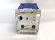
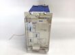
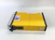
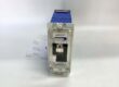
- Hardware Type: Full withdrawable plug-in static single-phase AC voltage relay, yellow aluminum Midos chassis, front dual rotary adjustment dials for over/undervoltage thresholds
- Key Feature: B-series medium burden 110/125VDC auxiliary coil, direct PT secondary AC voltage input, independent adjustable overvoltage / undervoltage trip setpoints with fixed definite time delay
- Primary Field Use: Monitor single-phase PT-derived AC bus voltage to trigger overvoltage insulation trip, undervoltage motor stall alarm and generator excitation collapse protection.
Hard-Numbers: Technical Specifications
- Protocol Support: Static analog sampling hardware, no digital bus communication; dry volt-free pre-alarm / trip changeover contacts
- Port Count: Single PT AC voltage input terminals, DC auxiliary coil supply terminals, separate alarm and trip contact terminal blocks
- Baud/Data Rate: No serial data transmission
- Operating Temperature: -10°C to +55°C cabinet operational; -40°C to +85°C storage
- Isolation Rating: 2000Vrms dielectric withstand between AC PT measurement circuits and trip contact wiring
- Power Draw: Medium burden B coil, balanced DC battery load for densely packed multi-relay panels
- Auxiliary DC Supply: 110/125 VDC station control battery, stable operation at 75%–120% rated voltage
- AC PT Input Range: 0–130% nominal system PT secondary voltage, 50/60Hz auto-adaptive
- Undervoltage Adjustment Band: 40%–80% nominal AC voltage via front rotary dial
- Overvoltage Adjustment Band: 105%–150% nominal AC voltage via front rotary dial
- Definite Trip Delay Window: 0.2s to 10s fixed time delay to suppress transient grid voltage blips
- Operate Response Time: ≤20ms contact state change once voltage crosses set threshold
- Contact Continuous Rating: 5A @300VDC resistive load; 40W DC inductive breaking capacity for breaker trip coils
- Physical Weight: 0.43kg fully assembled Midos draw-out unit
The Real-World Problem It Solves
Standard overcurrent MCGG relays only respond to overload and short-circuit current faults. They cannot track slow AC bus voltage drift; sustained undervoltage burns motor windings from reduced torque, while prolonged overvoltage accelerates transformer insulation breakdown long before overcurrent thresholds activate.External PT signal transmitters paired with standalone timing relays occupy two rack slots and drift calibration with cabinet heat and vibration every 6–12 months.Low-burden MVAW11L coils create unbalanced DC bus loading across packed protection panels. Simultaneous multi-feeder faults trigger localized DC bus sag and intermittent relay dropout, disabling voltage protection logic.Non-Midos MVUA11 panel mount relays lack integrated CT shorting terminals; swapping them requires full CT wiring disconnection, creating lethal open CT surge hazards during maintenance.Where you’ll typically find it:
- Fossil power plant generator auxiliary PT bus over/undervoltage protection panels
- Refinery MV motor MCC low AC supply stall and overvoltage insulation trip schemes
- Urban distribution substation transformer secondary bus voltage collapse monitoring cabinetsThis single draw-out unit integrates PT voltage sensing, dual adjustable trip thresholds and time delay to eliminate external signal transmitters and stabilize DC panel loading during mass fault events.
Hardware Architecture & Under-the-Hood Logic
This unit uses isolated AC PT signal conditioning front-end paired with fixed-function static measurement logic, no user programmable microprocessor code. It shares standardized Midos rack mechanical design with all ALSTOM Midos protection hardware for unified cabinet layout.
- Single-phase PT secondary AC voltage feeds filtered isolated sampling circuitry to block substation VFD and breaker switching EMI noise from field wiring.
- Onboard voltage divider network continuously samples RMS AC voltage values, compares measured magnitude against two independent front dial setpoints for overvoltage and undervoltage.
- Internal fixed-time timer activates once AC voltage crosses either threshold; timer elapse switches contact state to avoid nuisance alarms from momentary grid voltage transients.
- Medium-wattage B-series coil winding balances total DC load draw on station battery, preventing uneven voltage sag across multi-relay panels during concurrent fault events.
- Front panel LED indicators display healthy auxiliary supply, undervoltage pre-alarm active, overvoltage fault latched status for quick on-site visual diagnostics without workstation access.
- Rear Midos rack terminal base integrates factory CT short-circuit jumpers; full chassis withdrawal possible without disconnecting CT secondary wiring to eliminate lethal open CT kilovolt surge hazards.
Field Service Pitfalls: What Rookies Get Wrong
Swapping MVAW11L Low-Burden Coil Variant For MVAW11B Medium-Burden Unit
New technicians pull MVAW11L spare stock without matching model suffix. During multi-feeder simultaneous faults, uneven DC load creates localized bus sag; low-burden coils dropout prematurely, motors and generators run unprotected against dangerous voltage deviation conditions.Field Rule: MVAW11B medium-burden variant mandatory for dense multi-relay protection panels; segregate B and L coil MVAW11 spares in clearly labeled locked storage bins.
Skipping CT Short Jumper Installation Before Withdrawing Draw-out Relay
Apprentices pull the relay chassis straight out without shorting CT terminals on the rack base. Open CT secondary windings generate kilovolt surge that damages upstream MCGG overcurrent relay sampling boards and creates cabinet electric shock hazard.Quick Fix: Always install factory CT short-circuit jumpers on the Midos base terminal strip before removing any draw-out MVAW voltage protection relay unit.
Misadjusting Over/Undervoltage Threshold Without Cross-Checking Transformer/Generator Data Sheets
Maintenance crews randomly turn the front dial during spare replacement without referencing equipment voltage operating limits. Overly tight setpoints trigger constant nuisance trips during normal grid voltage fluctuations; overly wide setpoints fail to catch sustained dangerous voltage collapse or overexcitation conditions.Field Rule: Record undervoltage trip value, overvoltage trip value and delay time on the relay door label after every setting change; cross-verify against equipment protection scheme drawing before returning the relay online.
Routing PT AC Signal Cable Parallel To MV Power Cables
Apprentices run unshielded PT wiring alongside medium voltage feeder cables. Inductive EMI distorts AC voltage measurement readings, relay trips randomly during breaker switching events.Field Rule: Separate PT signal wiring into dedicated control cable trays; use shielded twisted pair for all PT circuits, single-point ground shield at the PT cubicle only.
Commercial Availability & Pricing Note
Please note: The listed price is for reference only and is not binding. Final pricing and terms are subject to negotiation based on current market conditions and availability.