

Component Snapshot At-a-Glance
- Model: 3531E
- Alt. P/N: No official factory cross-reference replacement part number
- Product Series: Triconex Tricon V9/V10/V11 SIL3 TMR SIS rack platform
- Hardware Type: Rack-mounted triple redundant discrete digital input module, 32 fully independent non-grouped field channels
- Key Feature: Full per-channel galvanic separation, no shared common return bus; no native open-wire diagnostic hardware (core difference from diagnostic 3501E)
- Primary Field Use: Collect 115VAC/DC motor auxiliary contact and high-voltage valve position feedback inside refinery, power plant SIS and ITCC cabinets
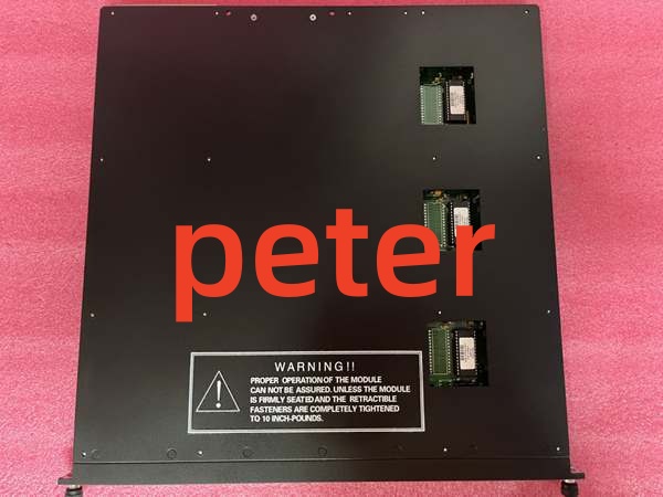
Triconex 3531E
Hard-Numbers: Technical Specifications
- Nominal Input Voltage: 95~130VAC/DC dry/wet contact rated field input
- Channel Count: 32 fully standalone input channels, zero grouped common terminal banks
- Isolation Rating: 1500VAC dielectric isolation per single channel to backplane bus
- Operating Temperature: -40°C ~ +70°C continuous cabinet operation; -40°C ~ +85°C storage temperature limit
- Backplane Power Draw: 5.6W nominal steady-state rack bus power consumption
- Input Switch Latency: OFF→ON ≤9ms, ON→OFF ≤16ms fixed hardware filter delay
- Safety Certification: IEC61508 SIL3, UL Class I Div2, ATEX Zone 2 hazardous location approval
- Unit Physical Weight: 1.50kg fully assembled rack module
- Ambient Humidity: 5%~95%RH non-condensing closed cabinet operating environment only
The Real-World Problem It Solves
Standard 48V DI hardware cannot directly terminate plant-wide 115V auxiliary motor contacts, forcing costly intermediate interposing relays that add extra failure points to safety circuits. Diagnostic-enabled 115V cards like 3501E carry higher spare pricing for low-priority auxiliary feedback loops.
Where you’ll typically find it:
- Petrochemical plant pump house SIS racks capturing 115V motor run/auxiliary contact status
- Combined cycle power plant BMS cabinets monitoring boiler fan motor safety interlock switches
- Offshore FPSO auxiliary shutdown racks for 115V solenoid valve mechanical limit feedback
Independent channel layout eliminates cross-circuit leakage while cutting relay installation and spare inventory overhead for high-voltage field feedback loops.
Hardware Architecture & Under-the-Hood Logic
Passive opto-isolated triple redundant PCB design without local onboard microcontroller; three fully segregated sampling circuits run parallel to contain single-path component faults away from remaining TMR lanes.
- Field 115V AC/DC contact signals route from dedicated termination base via ribbon cable into module front header per isolated channel pin.
- Every incoming input signal splits evenly across three separate optocoupler sampling legs for independent voltage threshold measurement on each redundant lane.
- Fixed onboard analog comparator executes hardware 2oo3 voting to filter transient cabinet EMI and single TMR leg component drift errors.
- Validated binary channel status transmits over proprietary TriBus backplane to rack main CPU for safety logic processing.
- Front panel channel LED lights solid green for valid closed contact; red illuminates for overvoltage or field shorted wiring conditions.
- No embedded diagnostic pulse circuitry; floating unused channels produce no onboard fault alert from module hardware.

Triconex 3531E
Field Service Pitfalls: What Rookies Get Wrong
Mixing 115V and 48V Field Wiring on Adjacent TerminalsNew technicians run leftover 48VDC field cables alongside 115V channels on matching termination strips. Voltage differential creates capacitive coupling that triggers random false input closure tags across nearby unused points.
- Quick Fix: Segregate 115V and low-voltage wiring onto physically separated terminal rails; never bundle differing nominal voltage circuits on one baseboard.
Leaving Spare Input Terminals Open Without Bleeder LoadsField crews leave unused 3531E channel terminals floating bare with no termination resistors. High cabinet stray EMI from nearby VFD cables induces phantom voltage and intermittent random channel ON triggers during load swings.
- Field Rule: Install 2kΩ 5W bleeder resistors across all vacant input terminals to suppress floating induced voltage pickup.
Hot-Swap Energized Module With Live 115V Field Feed ConnectedMaintenance pulls installed 3531E while field 115V supply remains hot on termination base. Reverse feed voltage damages internal optocoupler legs and locks affected channels into permanent FAULT state.
- Quick Fix: Cut all field-side 115V circuit breakers and verify zero terminal voltage via multimeter before module extraction or rack slot reseating.
Commercial Availability & Pricing Note
Please note: The listed price is for reference only and is not binding. Final pricing and terms are subject to negotiation based on current market conditions and availability.


