

Component Snapshot At-a-Glance
- Model: FBM205
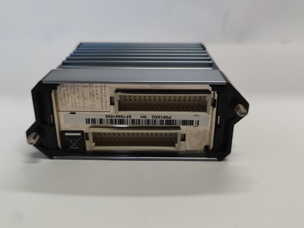
- Alt. P/N: No factory alternate card; matched termination base = P0916AJ
- Product Series: Foxboro I/A Series DCS, FBM200 mixed analog I/O lineup
- Hardware Type: Single-slot rack mount mixed 4-channel AI + 4-channel AO redundant-capable analog module, per-channel galvanic isolation
- Key Feature: Native HART pass-through on all 8 channels, supports paired redundant hot-standby module installation on single TA base
- Primary Field Use: Pair field 2-wire transmitters and modulating control valves on critical process loops to cut separate AI/AO rack slot consumption.
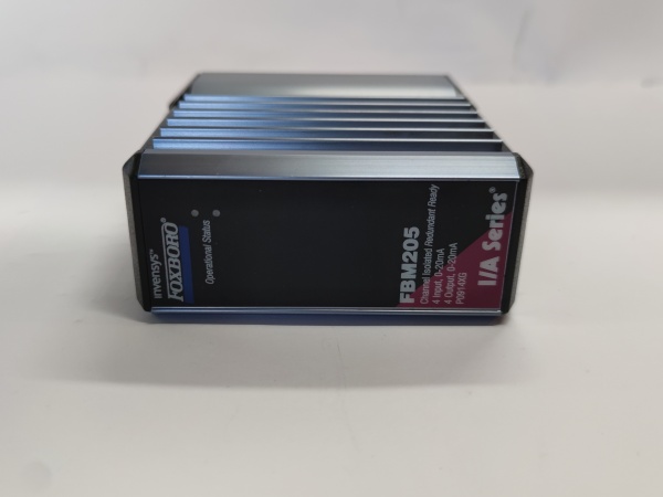
Foxboro FBM205
Hard-Numbers: Technical Specifications
- Protocol Support: Redundant 2Mbps Nodebus HDLC backplane + HART 31.25kbps field signal overlay
- Port Count: 4 x 4–20mA Analog Input + 4 x 4–20mA Analog Output (8 total isolated channels)
- Baud/Data Rate: Fixed 2Mbps cyclic Nodebus rack scan; HART field comm fixed 31.25kbps
- Operating Temperature: -20°C ~ +70°C operational; -40°C ~ +85°C storage rating, ISA G3 harsh environment qualified
- Isolation Rating: 1500VAC per-channel galvanic isolation, channel-to-backplane separated via internal optocoupler barriers
- Power Draw: 4.5W nominal single module; max 10W total for redundant dual-card pairing
- Signal Range: 0–20.4mA DC factory calibrated, standard 4–20mA process span mapping in DCS software
- ADC Resolution: 16-bit sigma-delta per input channel, typical accuracy ±0.05% full scale
- Terminal Wire Rating: P0916AJ accepts max 1.5mm² stranded copper per screw terminal
- Fail-Safe Logic: Software-configurable AO fail freeze/zero output on module backplane loss
The Real-World Problem It Solves
Stacking standalone FBM201 AI and FBM237 AO cards eats extra rack slots for single control loops, forcing oversized I/O cabinets and bloated spare part inventories for critical unit controls. Unmatched separate termination bases also introduce extra wiring junction points that spawn intermittent PV drift and valve hunting mid-process run.
Where you’ll typically find it:
- Refinery reactor feed flow/modulating control valve critical loop consolidated I/O racks
- Thermal power plant boiler feedwater drum level control DCS cabinet assemblies
- Natural gas plant scrubber pressure PID control transmitter + globe valve field wiring panels
Combined 4AI/4AO layout halves required rack slots per closed control loop and eliminates unnecessary intermediate terminal junctions to lower unplanned alarm frequency.
Hardware Architecture & Under-the-Hood Logic
uses a single onboard dedicated RISC processor handling all channel ADC/DAC conversion, HART data parsing and Nodebus packet assembly; no shared channel processing between input and output banks, each channel carries independent isolation circuitry from backplane power rail. Dual-card redundant setup shares one P0916AJ base with common field wiring for automatic hot swap.
- Field 4–20mA transmitter analog signal feeds into assigned AI channel opto-isolation front end on module PCB.
- 16-bit sigma-delta ADC converts analog current to digital register value, embedded HART modem strips superimposed digital instrument data off analog waveform.
- Onboard CPU compiles all four AI register values and outgoing four AO setpoints into standard Nodebus payload per rack scan cycle.
- Received DCS output setpoint converts via DAC to proportional 4–20mA drive signal routed out AO channel to field modulating valve actuator.
- Redundant standby module mirrors all field signal readings continuously; primary fault triggers seamless output handoff without field signal interruption.
Foxboro FBM205
Field Service Pitfalls: What Rookies Get Wrong
New technician mounts onto P0916FH (FBM240 base); pinout mismatch misroutes 24VDC loop power into AO output circuitry, burns internal output driver ICs instantly.
- Field Rule: Restrict exclusive pairing only with factory specified P0916AJ termination assembly, zero cross-compatibility with other FBM TA variants.
Parallel routing of high-current AC cable alongside HART signal wiringField crew runs 480V motor power cable in same tray as ’s HART instrument wiring; induced EMI corrupts HART digital data and causes random PV jump/valve oscillation.
- Quick Fix: Separate AC power and analog/HART signal cabling by minimum 15cm physical gap per ISA S50.12 wiring standard.
Tech removes primary live without disabling DCS control tags first; standby module transient load spike triggers momentary AO output drop and unplanned process upset.
- Field Rule: Place associated control loops into manual mode inside Foxboro Control Builder before removing either card in redundant pair.
Commercial Availability & Pricing Note
Please note: The listed price is for reference only and is not binding. Final pricing and terms are subject to negotiation based on current market conditions and availability.


