Product Core Brief
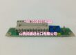
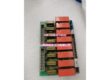
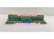
- Model: DSQC355A
- Brand: ABB
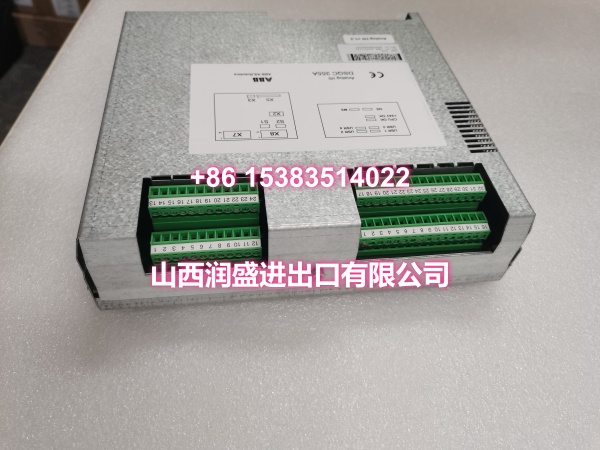
- Series: ABB IRC5 Robot Controller Analog I/O Module
- Core Function: 4-channel analog input + 4-channel analog output unit for ABB IRC5 controllers, enabling precise pressure, temperature, and displacement signal acquisition and control.
- Product Type: Analog I/O Unit (AI/AO Module)
- Key Specs: 4AI (-10V~+10V / 4-20mA) + 4AO (3× -10V~+10V, 1× 4-20mA) | 100Hz Sampling | DeviceNet Bus | DIN Rail Mount
- Note: Condition: New Original (New Surplus). Address range 10-63 (0-9 reserved for system).
Key Technical Specifications
| Parameter | Value |
|---|---|
| Device Model | |
| Device Type | Analog I/O Unit |
| Series | ABB IRC5 Robot Controller I/O Module |
| Communication Protocol | DeviceNet (IEC 62026-3) |
| Analog Input Channels | 4 channels |
| Analog Input Signal | -10V to +10V voltage / 4-20mA current |
| Analog Output Channels | 4 channels (3× voltage, 1× current) |
| Analog Output Signal | 3× -10V to +10V, 1× 4-20mA |
| Input Accuracy | Voltage ±0.1% FS, Current ±0.2% FS |
| Output Accuracy | Voltage ±0.2% FS, Current ±0.3% FS |
| Input Impedance | Voltage ≥10MΩ, Current 250Ω |
| Output Load | Voltage ≤10mA, Current load ≤500Ω |
| Sampling/Update Rate | 100Hz (input and output) |
| Power Supply | DC 24V ±10% |
| Operating Temperature | 0°C to +45°C |
| IP Rating | IP20 (module body) |
| Mounting | DIN rail (35mm) |
| Address Range | 10-63 (DeviceNet, 0-9 reserved) |
| Weight | Approx. 0.5-0.8 kg |
| Compatible Controllers | ABB IRC5 series |
| Typical Applications | Vacuum pressure monitoring, spray pressure control, bending force measurement, servo valve control |
| Condition | New Original (New Surplus) |
Product Introduction
The ABB DSQC355A is a dedicated analog I/O unit for ABB IRC5 robot controllers, providing 4 analog input channels and 4 analog output channels for precise continuous signal acquisition and control. It connects to the IRC5 controller via the DeviceNet fieldbus protocol, enabling the robot to interface with analog sensors and actuators in automated production environments.
In industrial applications, robots often need to handle continuous analog signals rather than simple on/off digital signals. The DSQC355A addresses this need by supporting both voltage (-10V to +10V) and current (4-20mA) signal types on its input channels, allowing direct connection to pressure transducers, temperature sensors, displacement sensors, and other analog measurement devices. The output channels include three voltage outputs and one dedicated current output, enabling the robot to control proportional pressure valves, servo valves, variable frequency drives, and other analog-controlled actuators.
The module’s 100Hz sampling and update rate ensures real-time signal processing, critical for closed-loop control applications such as spray painting pressure regulation, vacuum gripping force monitoring, and bending force control. Each channel can be independently configured through RobotStudio software to match the connected sensor or actuator type, eliminating the need for hardware changes when switching between different signal standards.
The DSQC355A uses standard DeviceNet communication (conforming to IC 62026-3), with an address range of 10-63 (addresses 0-9 are reserved for system use). This allows seamless integration into the IRC5 controller’s I/O architecture alongside other DeviceNet modules such as DSQC651 and DSQC652. The module mounts on a standard 35mm DIN rail inside the control cabinet, with an IP20 rating suitable for standard industrial cabinet environments.
Common applications include:
- Vacuum gripping systems: Monitoring vacuum pressure via analog input to confirm successful part pickup before proceeding with robot motion.
- Spray painting cells: Reading spray gun pressure and flow rate signals, outputting control signals to regulate paint flow and atomization pressure.
- Bending and forming: Measuring bending force in real-time to adjust robot position and prevent material damage.
- Servo valve control: Outputting analog signals to control proportional hydraulic or pneumatic valves for precise force and position control.
For maintenance teams supporting IRC5 installations, the DSQC355A is a direct drop-in replacement for failed or degraded analog I/O modules. When replacing, verify the DeviceNet address configuration and channel signal type settings match the original module to ensure seamless integration without reconfiguration.
QA & Testing SOP
Every unit goes through a structured verification process before shipment:
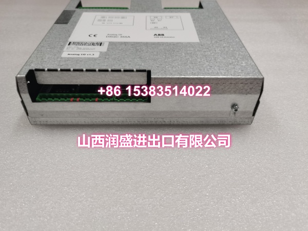
- Visual Inspection: Check the PCB for cracks, burnt components, corrosion on connector pins, and physical damage to the board. Verify that all components (terminal blocks, DIP switches, surface-mount ICs) are securely mounted with no cold joints or solder bridges. Inspect the module housing and DIN rail mounting clips for damage.
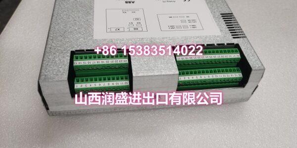
- Connector Pin Verification: Inspect all terminal block connectors (X7 for analog output, X8 for analog input, X5 for DeviceNet communication) for straightness, corrosion, or bending. Verify that the DeviceNet connector (X5) pins are intact, as bent pins cause communication failures on the fieldbus.
- Power-On Self-Test: Connect the module to a DC 24V power supply and verify that the power LED illuminates correctly. Check for any abnormal heating during the initial power-on.
- DeviceNet Communication Test: Connect the module to a DeviceNet network and verify that the master station can establish communication at the configured address (10-63). Confirm that the module is recognized and that no communication fault codes are reported.
- Analog Input Test: Apply known voltage (-10V to +10V) and current (4-20mA) signals to each input channel and verify that the module correctly reads the values within the specified accuracy (±0.1% FS for voltage, ±0.2% FS for current). Check for channel-to-channel crosstalk.
- Analog Output Test: Command each output channel to produce specific voltage and current values and verify the output with a multimeter or oscilloscope. Confirm that the three voltage outputs and one current output operate within the specified accuracy (±0.2% FS for voltage, ±0.3% FS for current).
- Channel Configuration Test: Verify that each channel can be independently configured for voltage or current mode through software, and that the configuration persists after power cycling.
- Anti-Counterfeit & Packaging: Verify authenticity markings on the PCB and components. Each unit is shipped in anti-static protective packaging with desiccant to prevent moisture absorption and connector oxidation during transit.
Installation Pitfalls & Guide
Installing or replacing an analog I/O module requires careful attention to signal wiring, shielding, and network configuration.
❗ Power-Down Before Installation: Always disconnect power to the IRC5 controller and the DeviceNet network before removing or inserting the DSQC355A module. Although DeviceNet supports some hot-swap capability, it is strongly recommended to replace the module with power off to prevent electrical damage to the module or the network.
❗ Anti-Static Protection: Always wear an anti-static wrist strap when handling the DSQC355A module. The PCB contains sensitive analog-to-digital and digital-to-analog converter ICs that can be damaged by electrostatic discharge (ESD). Handle the module by its edges only, avoiding contact with components or connector pins.
❗ Shielded Cable for Analog Signals: Analog signals are susceptible to electromagnetic interference. Always use shielded cables for analog input and output wiring, and connect the shield to ground at one end only (typically at the module end) to prevent ground loops. Avoid routing analog signal cables parallel to high-voltage power cables or motor cables.
❗ Verify DeviceNet Address: Before installing the replacement module, document the DeviceNet address from the original module. The DSQC355A supports addresses 10-63, with 0-9 reserved for system use. Setting the address to a reserved value or duplicating an existing device’s address will cause communication conflicts on the network.
❗ Signal Type Configuration: Each channel can be configured for voltage or current mode through RobotStudio software. Verify that the channel configuration matches the connected sensor or actuator type. Connecting a current-output sensor to a voltage-configured channel (or vice versa) will produce incorrect readings and may damage the module or sensor.
4-Step Replacement Guide:
- Pre-install: Document the existing DeviceNet address and channel signal type configuration from the original module. Back up the IRC5 controller’s I/O configuration, including the Unit Mapping and signal definitions. Verify the replacement module’s model (DSQC355A) matches the original. Prepare anti-static protection, tools, and a multimeter for verification.
- Removal: Disconnect power to the IRC5 controller and the DeviceNet network. Wear an anti-static wrist strap. Label all analog signal cables and the DeviceNet cable if not already labeled. Disconnect all wiring from the terminal blocks (X5, X7, X8). Release the module from the DIN rail and gently remove it. Inspect the DIN rail and terminal blocks for damage or debris.
- Install: Mount the new DSQC355A on the DIN rail, ensuring it is securely clipped in place. Configure the DeviceNet address to match the documented setting from the original module. Reconnect all analog signal cables to the correct terminals (X7 for output, X8 for input), verifying correct polarity and shield grounding. Reconnect the DeviceNet cable to the X5 connector. Double-check all connections before applying power.
- Power-on Test: Apply power to the IRC5 controller and the DeviceNet network. Verify that the module’s power LED illuminates and that no communication fault codes are reported by the controller. Use the teach pendant to verify that the analog I/O unit is recognized on the DeviceNet network and that channel configurations are correct. Test each input channel by applying a known signal and verifying the reading. Test each output channel by commanding a specific value and measuring the output. Monitor the module for several minutes to confirm stable operation.
Technical FAQ
1. What is the difference between DSQC355A and DSQC355? The DSQC355A is the IRC5-compatible version of the analog I/O card. The older DSQC355 (without the “A” suffix) was used with earlier ABB controller platforms (S4/S4C+) and is not directly compatible with IRC5 controllers. Users have reported that replacing a DSQC355A with a DSQC355 on an IRC5 controller results in communication failures, as the IRC5 requires the DSQC355A’s specific DeviceNet device definition. Always verify you are ordering the DSQC355A variant for IRC5 systems.
2. How many analog input and output channels does the DSQC355A provide? The DSQC355A provides 4 analog input channels and 4 analog output channels. The input channels support both voltage (-10V to +10V) and current (4-20mA) signals. The output channels include three voltage outputs (-10V to +10V) and one dedicated current output (4-20mA). Each channel can be independently configured through software.
3. What is the sampling rate of the DSQC355A? The DSQC355A has a sampling rate of 100Hz for analog inputs and an update rate of 100Hz for analog outputs. This means the module can read input signals and update output signals up to 100 times per second, providing sufficient bandwidth for most industrial process control applications such as pressure regulation, temperature monitoring, and force control.
4. Can the DSQC355A be used with OmniCore controllers? The DSQC355A is designed for ABB IRC5 series controllers. OmniCore controllers use a different I/O architecture and may require different module types (e.g., DSQC1030 for analog I/O). Always verify your controller model and consult ABB’s compatibility documentation before ordering replacement I/O modules.
5. What are common symptoms of a failing DSQC355A analog I/O module? Common symptoms include: Analog input readings that are erratic, drifting, or completely absent; analog output signals that do not match commanded values; DeviceNet communication fault codes reported by the IRC5 controller; module status LEDs indicating fault conditions; and channel-to-channel crosstalk where a signal on one channel affects readings on another channel. If you’re experiencing any of these symptoms, check the module’s LED indicators, verify wiring and shielding, and use the teach pendant’s diagnostic function to read the specific fault codes.
6. What’s the difference between New Surplus and Refurbished for analog I/O modules? We supply this unit as New Original (New Surplus)—unused, original factory stock. This comes with a standard 12-month warranty. Refurbished analog I/O modules carry risks including degraded analog-to-digital converter accuracy from prior operation, weakened terminal block contacts, and latent failures that may only manifest under full signal load conditions. For a module that directly interfaces with precision sensors and control actuators, new surplus is the safer choice.