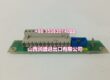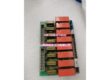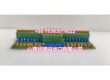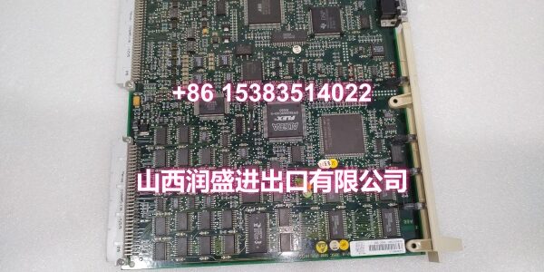
Product Core Brief
- Model: DSQC346B
- Brand: ABB
- Series: ABB Robot Drive System (S4 / S4C+ / M2000)
- Order Code: 3HAB8101-6 (common variant)
- Core Function: Axis drive unit for ABB robot controllers, converting DC bus power into precisely controlled AC power to drive individual robot axis servo motors.
- Product Type: Axis Drive Module (Servo Drive Unit)
- Key Specs: Rated DC 340V | Max DC 380V | 5kHz Switching Frequency | 2mH Required Phase Inductance | Operating Temp 0–70°C
- Note: Condition: New Original (New Surplus). Specific order code (e.g., 3HAB8101-6/xx) varies by revision and controller configuration.
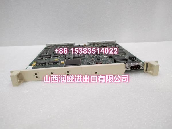
Key Technical Specifications
| Parameter | Value |
|---|---|
| Device Model | |
| Device Type | Axis Drive Unit / Motor Drive Module |
| Series | ABB Robot Drive System (S4 / S4C+ / M2000) |
| Common Order Code | 3HAB8101-6 |
| Rated DC Voltage | 340V DC |
| Maximum DC Voltage | 380V DC |
| Maximum Power Supply Voltage | 180V (AC side reference) |
| Rectifier Switching Frequency | 5kHz |
| Required Phase Inductance | 2mH |
| Operating Temperature | 0°C to +70°C |
| Maximum Heat Dissipation Temperature | 90°C |
| Mounting | Plug-in module in ABB controller drive rack |
| Communication Interface | Internal backplane bus (controller rack) |
| Protection Functions | Overcurrent, overvoltage, short-circuit, overtemperature protection |
| IP Rating | IP20 (inside control cabinet) |
| Weight | Approx. 2–3 kg (module only) |
| Compatible Controllers | ABB S4, S4C+, M2000 series robot controllers |
| Typical Applications | Axis motor drive for IRB6400, IRB6600, and other ABB industrial robots |
| Condition | New Original (New Surplus) |
Product Introduction
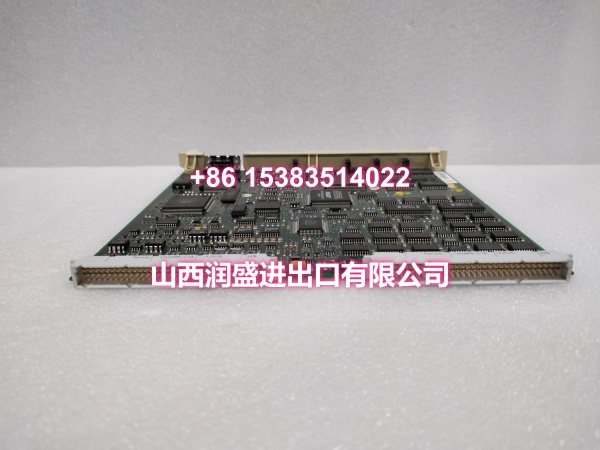
The ABB DSQC346B is an axis drive unit (motor drive module) designed for ABB robot controllers in the S4, S4C+, and M2000 series. It is a core component of the robot’s drive system, responsible for converting the DC bus voltage supplied by the rectifier unit (DSQC345) into precisely controlled AC power to drive the robot’s individual axis servo motors. Each DSQC346B module typically drives one or more axes, depending on the robot model and controller configuration.
The DSQC346B operates with a rated DC bus voltage of 340V and can handle up to 380V DC maximum. The module uses a 5kHz switching frequency for its rectifier/inverter stage, providing smooth and precise motor control with minimal torque ripple. The required phase inductance of 2mH ensures compatibility with ABB’s standard servo motors used across the IRB6400, IRB6600, and other robot families in the S4/S4C+ platform.
As part of the drive system module, the DSQC346B works in conjunction with the rectifier unit (DSQC345), the servo drive interface unit (ASDI), and the serial measurement unit (SMU) to form a complete servo drive chain. The rectifier converts incoming AC mains power to the DC bus voltage, the DSQC346B then inverts this DC power into controlled AC waveforms for each axis motor, and the SMU provides position feedback from the motor encoders back to the axis computer for closed-loop control.
The module features comprehensive protection functions including overcurrent, overvoltage, short-circuit, and overtemperature protection. These safeguards help prevent damage to the drive unit and the servo motors in the event of wiring faults, mechanical jams, or abnormal operating conditions. The module’s operating temperature range is 0°C to +70°C, with a maximum heat dissipation temperature of 90°C, making it suitable for standard industrial environments.
The DSQC346B plugs directly into the ABB controller’s drive rack and communicates with the axis computer via the internal backplane bus. This eliminates the need for external wiring between the controller and the drive modules, reducing installation complexity and improving signal integrity. The module is commonly found in ABB robot cells across automotive welding, material handling, palletizing, machining, and general assembly applications.
For maintenance teams supporting legacy ABB robot installations, the DSQC346B is a direct drop-in replacement for failed or degraded axis drive modules. When replacing a DSQC346B, always verify that the order code and revision match the original module to ensure compatibility with your specific robot model and controller configuration.
QA & Testing SOP
Every unit goes through a structured verification process before shipment:
- Visual Inspection: Check the PCB for cracks, burnt components, corrosion on connector pins, and physical damage to the board. Verify that all power components (IGBTs, capacitors, resistors), terminal blocks, and surface-mount components are securely mounted with no cold joints or solder bridges. Inspect the module housing for cracks or signs of overheating.
- Connector Pin Verification: Inspect all connector pins (backplane connectors, motor output terminals, DC bus terminals) for straightness, corrosion, or bending. Bent pins cause poor contact with the controller’s backplane or motor wiring, leading to intermittent drive faults or complete module failure.
- Power-On Self-Test: Install the module in a test controller rack and apply power. Verify that the module’s status LEDs illuminate correctly and that no fault codes are reported by the controller. Check for any abnormal heating of components during the initial power-on.
- DC Bus Voltage Test: Measure the DC bus input terminals to verify that the module correctly receives the expected DC voltage from the rectifier unit (approximately 340–380V DC depending on input AC voltage).
- Motor Output Test: Command the module to drive a test servo motor and verify that the output waveforms are correct using an oscilloscope. Check that the motor rotates smoothly without abnormal noise or vibration.
- Protection Function Test: Simulate overcurrent, overvoltage, and overtemperature conditions to verify that the module’s protection circuits activate correctly and that the controller receives the appropriate fault signals.
- Backplane Communication Test: Verify that the module is recognized by the controller’s axis computer and that position/speed commands are correctly received and executed.
- Anti-Counterfeit & Packaging: Verify authenticity markings on the PCB and components. Each unit is shipped in anti-static protective packaging with desiccant to prevent moisture absorption and connector oxidation during transit.
Installation Pitfalls & Guide
Installing or replacing an axis drive module requires careful attention to safety procedures and proper handling.
❗ Dangerous Voltage Warning: The drive unit contains hazardous voltages (up to 380V DC on the DC bus). Even after power is disconnected, dangerous voltage may remain on the rectifier board and throughout the drive unit due to capacitor charge. Always wait for the capacitors to fully discharge before handling the module. Verify zero voltage with a multimeter before proceeding.
❗ Power-Down Before Installation: Always disconnect power to the robot controller and wait for the DC bus capacitors to discharge before removing or inserting the DSQC346B module. Drive modules should be replaced with power off to prevent electrical damage to the module or the controller’s backplane connector.
❗ Anti-Static Protection: Always wear an anti-static wrist strap when handling the DSQC346B module. The PCB contains sensitive electronic components (IGBTs, gate drivers, control ICs) that can be damaged by electrostatic discharge (ESD). Handle the module by its edges only, avoiding contact with components or connector pins.
❗ Verify Order Code and Revision: Before installing the replacement module, verify that the order code (e.g., 3HAB8101-6) and revision match the original module. Different revisions may have different firmware or hardware configurations that are not compatible with your specific robot model or controller.
❗ Check Motor Wiring and Phase Sequence: Verify that the motor output wiring (U, V, W phases) is correctly connected to the corresponding motor terminals. Reversing the phase sequence can cause the motor to rotate in the wrong direction or trigger drive faults. Double-check all power and feedback connections before applying power.
4-Step Replacement Guide:
- Pre-install: Document the existing drive configuration, including the module’s order code, revision, and slot position in the controller rack. Back up the robot controller’s system parameters and calibration data. Verify the replacement module’s model (DSQC346B) and order code match the original. Prepare anti-static protection, tools, and a multimeter for verification.
- Removal: Disconnect power to the robot controller. Wait at least 5 minutes for the DC bus capacitors to discharge. Verify zero voltage on the DC bus terminals with a multimeter. Wear an anti-static wrist strap. Label all wiring connections if not already labeled. Disconnect the motor output cables and DC bus connections. Release the module’s retention mechanism and gently pull the module straight out of the controller rack. Inspect the controller’s backplane connector for damage or debris.
- Install: Align the new DSQC346B’s connector with the controller rack slot guides. Push firmly and evenly until fully seated. Secure the module with the retention mechanism. Reconnect the DC bus connections and motor output cables, verifying correct phase sequence (U, V, W) and terminal assignments. Double-check all connections before applying power.
- Power-on Test: Apply power to the robot controller. Verify that the module’s status LEDs indicate normal operation and that no drive fault codes are reported by the controller. Use the teach pendant to jog each axis driven by the module and verify smooth motor operation without abnormal noise or vibration. Run a calibration check to confirm that the axis position feedback is correct. Monitor the module for several minutes under load to confirm stable operation.
Technical FAQ
1. What is the difference between DSQC346B and DSQC346A/346G? The DSQC346 series includes multiple variants (DSQC346A, 346B, 346E, 346G, etc.) that differ in order code, revision, and specific hardware/firmware configurations. The DSQC346B (3HAB8101-6) is commonly used in S4/S4C+/M2000 controllers for specific robot models such as the IRB6400. Different variants may support different motor types, power ratings, or communication protocols. Always verify the exact order code and revision required for your specific robot model and controller configuration before ordering a replacement.
2. What is the rated DC voltage for the DSQC346B? The DSQC346B has a rated DC bus voltage of 340V DC and can handle up to 380V DC maximum. This DC voltage is supplied by the rectifier unit (DSQC345) in the controller’s drive system. The module converts this DC voltage into controlled AC waveforms to drive the robot’s servo motors.
3. What protection functions does the DSQC346B include? The DSQC346B includes comprehensive protection functions such as overcurrent protection, overvoltage protection, short-circuit protection, and overtemperature protection. These safeguards help prevent damage to the drive unit and the servo motors in the event of wiring faults, mechanical jams, or abnormal operating conditions. If any of these protection circuits are triggered, the module will shut down and report a fault code to the controller.
4. What are common symptoms of a failing DSQC346B drive module? Common symptoms include: Drive fault codes reported by the controller (e.g., overcurrent, overvoltage, IGBT fault); axis motor not responding to jog commands; motor rotating with abnormal noise or vibration; module status LEDs indicating fault conditions; intermittent drive faults that clear after power cycling; and the controller reporting communication errors with the axis computer. If you’re experiencing any of these symptoms, check the module’s LED indicators and use the teach pendant’s diagnostic function to read the specific fault codes.
5. Can the DSQC346B be used in IRC5 controllers? No, the DSQC346B is designed for ABB S4, S4C+, and M2000 series controllers. IRC5 controllers use a different drive system architecture with different module types (e.g., DSQC406, DSQC663, DSQC664). The DSQC346B is not compatible with IRC5 or OmniCore controllers. Always verify your controller model before ordering replacement drive modules.
6. What’s the difference between New Surplus and Refurbished for drive modules? We supply this unit as New Original (New Surplus)—unused, original factory stock. This comes with a standard 12-month warranty. Refurbished drive modules carry risks including degraded power components (IGBTs, capacitors) from prior operation, weakened protection circuits, and latent failures that may only manifest under full load conditions. For a module that directly drives your robot’s axis motors and is critical to production uptime, new surplus is the safer choice.