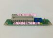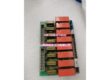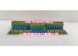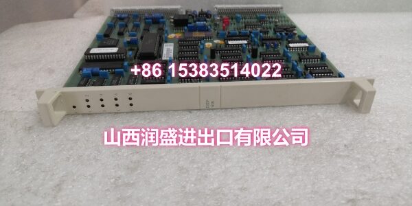
Product Core Brief
- Model: DSDP140A
- Brand: ABB
- Series: ABB Advant Master / S100 Series
- Core Function: High-precision counter board for counting and processing pulse signals from field devices such as flow meters, energy meters, and production counters.
- Product Type: Counter Board / Pulse Counter Module
- Key Specs: High-Precision Pulse Counting | Programmable Control | 24VDC Power Supply | Modular Rack-Mount Design | Industrial-Grade Reliability
- Note: Condition: New Original (New Surplus). Origin: Sweden.
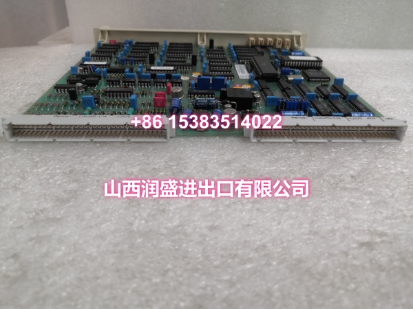
Key Technical Specifications
| Parameter | Value |
|---|---|
| Manufacturer Part Number | 57160001-ACT (also available: 57160001-KM) |
| Device Model | |
| Device Type | Counter Board / Pulse Counter Module |
| Series | ABB Advant Master / S100 Series |
| Function | High-precision counting and processing of pulse signals |
| Input Signal Type | Pulse signals from flow meters, energy meters, encoders, production counters |
| Power Supply | 24VDC (standard industrial voltage) |
| Structural Form | Modular, rack-mount |
| Installation | Control room installation (Advant Master / S100 backplane) |
| Processing | Programmable control with onboard signal processing |
| Operating Temperature | Industrial-grade (typically 0°C to +55°C) |
| Cooling Method | Passive (air-cooled) |
| Features | High-precision counting, programmable control, reliable operation |
| Typical Applications | Flow measurement, energy metering, production counting, process control |
| Origin | Sweden |
| Condition | New Original (New Surplus) |
Product Introduction
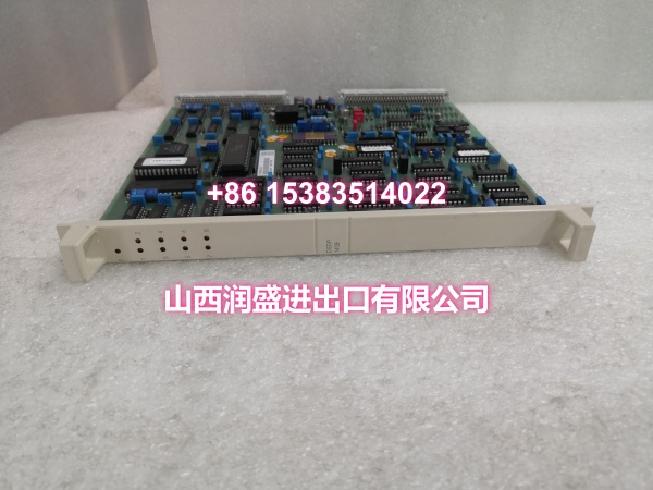
The ABB DSDP140A (order code 57160001-ACT / 57160001-KM) is a high-precision counter board designed for ABB’s Advant Master and S100 distributed control systems. It serves as a specialized interface module for counting and processing pulse signals from field measurement devices, enabling accurate measurement of flow, energy consumption, production output, and other cumulative process variables.
In industrial automation environments where precise measurement and cumulative counting are critical, the DSDP140A delivers reliable pulse counting performance with programmable control capabilities. The module accepts pulse signals from a variety of field devices including turbine flow meters, positive displacement meters, energy meters, rotary encoders, and production counting sensors. Its onboard processing capability handles signal conditioning, counting, and data transmission to the DCS controller, reducing the processing load on the main CPU.
The DSDP140A features a modular rack-mount design that integrates seamlessly into the Advant Master / S100 backplane architecture. Its 24VDC power supply is compatible with standard industrial power distribution systems. The module’s programmable control functionality allows engineers to configure counting parameters, set scaling factors for engineering unit conversion, and define alarm thresholds for abnormal counting conditions.
As an “intelligent” S100 I/O module, the DSDP140A performs signal processing and counting operations locally on the board rather than relying on the main controller’s CPU. This distributed processing architecture improves overall system real-time performance and ensures that high-frequency pulse signals are not missed during controller scan cycles.
For engineers maintaining legacy Advant Master or S100 installations, the DSDP140A is a direct drop-in replacement for failed or end-of-life counter boards. Its standardized form factor ensures compatibility with existing backplane configurations, avoiding costly mechanical rework or system redesign.
QA & Testing SOP
Every unit goes through a structured verification process before shipment:
- Visual Inspection: Check the module housing for cracks, corrosion on the backplane connector pins, and physical damage to the PCB. Verify that any status LED indicators are intact and undamaged.
- Connector Pin Verification: Inspect the backplane connector pins for straightness, corrosion, or bending. Bent pins cause poor contact with the backplane, leading to intermittent communication failures or complete module malfunction.
- Power-On Self-Test: Apply 24VDC power and verify that the module’s status LED indicates normal operation. A red or flashing LED indicates a hardware fault or configuration mismatch.
- Pulse Counting Test: Using a pulse signal generator, apply test pulses at various frequencies to verify that the module accurately counts input pulses. Compare the module’s reported count against the known input to verify counting accuracy.
- Programmable Parameter Verification: Where test infrastructure allows, verify that the module accepts and retains programmable parameters such as scaling factors, counting direction, and alarm thresholds.
- Anti-Counterfeit & Packaging: Verify authenticity markings on the module body and PCB. Each unit is shipped in anti-static protective packaging with desiccant to prevent moisture absorption and connector oxidation during transit.
Installation Pitfalls & Guide
Installing or replacing a counter board requires careful attention to signal wiring and configuration.
❗ Power-Down Before Installation: Always disconnect power to the rack or I/O section before removing or inserting the DSDP140A module. Counter boards should be replaced with power off to prevent transient spikes from damaging the module or connected field devices.
❗ Signal Wiring Verification: Before connecting field wiring to the new module, verify that each wire is correctly labeled and corresponds to the documented channel assignment. Pulse signal wiring must use shielded cables to prevent electromagnetic interference from causing false counts. Route signal cables separately from power cables, maintaining at least 30cm distance.
❗ Shielded Cable Grounding: For pulse signal wiring, use shielded cables with the shield grounded at the control cabinet end only. Grounding at both ends creates ground loops that can introduce noise into the pulse signals, causing false counts or missed pulses.
❗ Configuration Parameter Matching: Before powering on the replacement module, verify that the counting parameters (scaling factor, counting direction, alarm thresholds) are correctly configured to match the original module’s settings. Incorrect scaling factors will cause inaccurate engineering unit readings in the DCS.
❗ Pulse Frequency Compatibility: Verify that the pulse frequency from your field devices is within the DSDP140A’s counting range. Exceeding the maximum counting frequency can cause missed pulses and inaccurate measurements.
4-Step Replacement Guide:
- Pre-install: Document the existing counting configuration (scaling factors, alarm thresholds, channel assignments). Back up the DCS project. Verify the replacement module’s part number (57160001-ACT or 57160001-KM) matches the original. Prepare anti-static protection and tools.
- Removal: Disconnect power to the I/O rack. Wear an anti-static wrist strap. Disconnect all field wiring from the terminal block and label each wire with its channel number. Loosen the module retention screws. Gently pull the module straight out of the backplane slot. Inspect the backplane connector for damage.
- Install: Align the new DSDP140A’s connector with the backplane slot. Push firmly and evenly until fully seated. Tighten retention screws. Reconnect field wiring to the correct terminals according to the documented channel assignments. Verify that all connections are secure and properly torqued. Configure the counting parameters to match the original settings.
- Power-on Test: Apply power to the rack. Verify that the module’s status LED indicates normal operation. Enter the DCS diagnostic screen and confirm that the module is recognized with no fault codes. Apply a known pulse signal to verify that the module counts accurately and reports correct values to the DCS. Monitor for several minutes to confirm stable operation.
Technical FAQ
1. What types of field devices can the DSDP140A connect to? The DSDP140A is designed to accept pulse signals from a variety of field measurement devices, including turbine flow meters, positive displacement meters, energy meters, rotary encoders, proximity switches used for production counting, and other pulse-generating sensors. The key requirement is that the field device outputs a clean pulse signal compatible with the module’s input specifications.
2. What’s the difference between the DSDP140A and DSDP140B? Both the DSDP140A and DSDP140B are counter boards for ABB’s Advant Master / S100 systems, but they have different order codes and may have different technical specifications. The DSDP140A uses order codes such as 57160001-ACT and 57160001-KM, while the DSDP140B uses order code 57160001-ACX. When replacing a counter board, always verify that the replacement model matches the original to ensure compatibility with your system configuration.
3. Can the DSDP140A be used with ABB’s newer AC 800M or 800xA systems? The DSDP140A is designed for ABB’s Advant Master and S100 series systems. It is not directly compatible with newer platforms like AC 800M or 800xA, which use different backplane architectures and I/O module form factors (such as the S800 I/O system). If you’re migrating to a newer system, you’ll need to use the corresponding counter modules designed for that platform.
4. What does “programmable control” mean for the DSDP140A? The DSDP140A’s programmable control functionality allows engineers to configure counting parameters such as scaling factors (to convert raw pulse counts into engineering units like liters, kWh, or pieces), counting direction (up or down), alarm thresholds for abnormal counting conditions, and filtering settings to reject noise. These parameters are typically configured through the DCS configuration software and downloaded to the module.
5. What’s the difference between New Surplus and Refurbished for counter boards? We supply this unit as New Original (New Surplus)—unused, original factory stock. This comes with a standard 12-month warranty. Refurbished counter boards carry risks including degraded connector contacts from previous insertion cycles, latent counting errors that may only manifest at high pulse frequencies, and undocumented firmware version mismatches. For a module that directly affects measurement accuracy and process data integrity, new surplus is the safer choice.