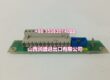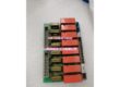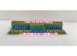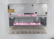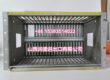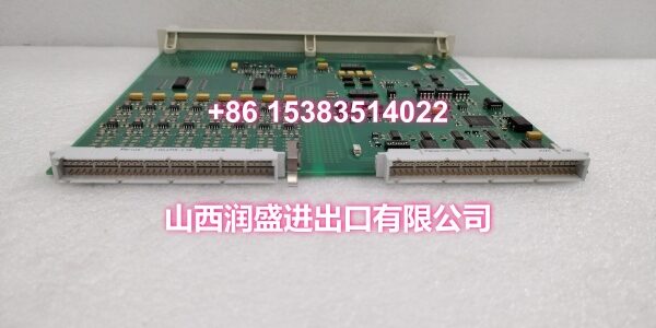
Product Core Brief
- Model: DSBB175
- Brand: ABB
- Series: ABB Advant Master / MasterPiece 200 Series
- Core Function: High-performance MXB bus backplane module serving as the main data and power backbone for Advant Master and MasterPiece 200 distributed control systems.
- Product Type: MXB Bus Backplane Module
- Key Specs: 12–24VDC Power Supply | Up to 2A per Channel | <100 mΩ Contact Resistance | Passive Air Cooling | DIN Rail Mounting | LED Diagnostics | Dust/Moisture Protection
- Note: Condition: New Original (New Surplus). Origin: Sweden/Switzerland.
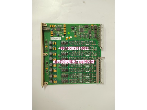
Key Technical Specifications
| Parameter | Value |
|---|---|
| Manufacturer Part Number | 57310256-ER |
| Device Model | |
| Device Type | MXB Bus Backplane Module |
| Series | ABB Advant Master / MasterPiece 200 Series |
| Function | Data and power distribution backbone |
| Power Supply | 12–24VDC |
| Current Rating | Up to 2A per channel |
| Contact Resistance | <100 mΩ |
| Operating Temperature | –20°C to +60°C |
| Cooling Method | Passive (air-cooled) |
| Mounting | DIN rail |
| Dimensions | 160 × 100 × 50 mm |
| Weight | 0.2 kg |
| Features | LED indicators, dust/moisture protection |
| Typical Applications | Advant Master DCS, MasterPiece 200 systems, process control, power generation, oil & gas |
| Origin | Sweden/Switzerland |
| Condition | New Original (New Surplus) |
Product Introduction
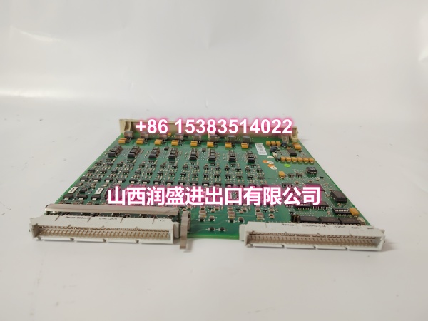
The ABB DSBB175 (order code 57310256-ER) is a high-performance MXB bus backplane module engineered to serve as the backbone for ABB’s Advant Master and MasterPiece 200 distributed control systems. It efficiently distributes power and enables seamless communication between CPU, I/O, and communication modules, forming the critical infrastructure that holds the control system together.
In industrial automation environments, the backplane is the unsung hero of system reliability. The DSBB175 guarantees stable and reliable signal transmission across all controller modules mounted on it, ensuring that critical process data flows without interruption between the processor, analog/digital I/O cards, and communication interfaces. Its robust mechanical design provides structural support for all connected modules while maintaining low contact resistance (<100 mΩ) to minimize voltage drop and signal degradation.
The module features a compact DIN rail mounting design (160 × 100 × 50 mm), making it suitable for space-constrained control cabinet installations. It operates on 12–24VDC and supports passive air cooling, eliminating the need for fans and reducing maintenance requirements. Integrated LED indicators provide quick visual diagnostics for power and communication status, while built-in dust and moisture protection maintains long-term operational integrity in harsh industrial environments.
For engineers maintaining or upgrading legacy Advant Master or MasterPiece 200 installations, the DSBB175 is a direct drop-in replacement for failed or degraded backplane modules. Its standardized form factor ensures compatibility with existing module configurations, avoiding costly system redesign or mechanical rework.
QA & Testing SOP
Every unit goes through a structured verification process before shipment:
- Visual Inspection: Check the module housing for cracks, corrosion on the DIN rail mounting clips, and physical damage to the PCB. Verify that LED indicator lenses are intact and undamaged.
- Connector Pin Verification: Inspect the backplane connector pins for straightness, corrosion, or bending. Bent pins cause poor contact with mounted modules, leading to intermittent communication failures or power delivery issues.
- Contact Resistance Test: Using a milliohm meter, verify that contact resistance across key power and signal paths is below 100 mΩ. Elevated resistance indicates worn or oxidized contacts that could cause voltage drop or signal integrity problems.
- Power-On Self-Test: Apply 12–24VDC power and verify that the module’s status LED indicates normal operation. A red or flashing LED indicates a hardware fault or power delivery issue.
- Mounting Clip Integrity: Verify that the DIN rail mounting clips are functional and not deformed. Damaged clips can cause the module to sit loose on the rail, leading to vibration-induced connection failures.
- Anti-Counterfeit & Packaging: Verify authenticity markings on the module body and PCB. Each unit is shipped in anti-static protective packaging with desiccant to prevent moisture absorption and connector oxidation during transit.
Installation Pitfalls & Guide
Installing or replacing a backplane module requires careful attention to mechanical alignment and electrical safety.
❗ Power-Down Before Installation: Always disconnect power to the entire rack or DIN rail section before removing or inserting the backplane module. Unlike I/O cards that may support hot-swap in some configurations, the backplane itself carries main power distribution and should never be manipulated while energized.
❗ DIN Rail Alignment: When mounting the DSBB175 on the DIN rail, ensure the top clip engages first, then press the bottom of the module firmly until the lower clip snaps into place. Forcing the module without proper alignment can damage the mounting clips or cause the module to sit at an angle, compromising mechanical stability.
❗ Module Seating Verification: After installing the backplane, verify that all CPU, I/O, and communication modules are fully seated in their respective slots. Loose module-to-backplane connections are a leading cause of intermittent communication faults and channel dropouts in DCS systems.
❗ Grounding Verification: Ensure the DIN rail itself is properly bonded to the control cabinet grounding system. The backplane relies on the DIN rail ground reference for EMI suppression and safety. A floating or high-impedance ground can introduce noise into analog signals and cause erratic module behavior.
❗ Environmental Protection: While the DSBB175 includes dust and moisture protection, avoid installing it in locations where it will be directly exposed to water spray, excessive dust accumulation, or corrosive gases. These conditions can degrade connector contacts and LED indicators over time.
4-Step Replacement Guide:
- Pre-install: Document the existing module configuration (which modules are in which slots). Back up the DCS project. Verify the replacement backplane’s part number (57310256-ER) matches the original. Prepare anti-static protection and tools.
- Removal: Disconnect power to the DIN rail section. Remove all mounted modules (CPU, I/O, communication cards) and set them aside in a safe, static-free location. Release the DIN rail mounting clips and remove the old backplane. Inspect the DIN rail for damage or corrosion.
- Install: Mount the new DSBB175 on the DIN rail, ensuring proper clip engagement. Reinstall all modules in their documented positions, verifying each one is fully seated. Tighten any module retention screws. Reconnect power.
- Power-on Test: Apply power and verify the backplane’s status LED indicates normal operation. Check each mounted module’s status LED for normal operation. Enter the DCS diagnostic screen and confirm no hardware fault codes. Verify communication with all I/O channels before returning to normal operation.
Technical FAQ
1. What’s the difference between a backplane module and a shield board? The DSBB175 is an active MXB bus backplane module that distributes power and data between CPU, I/O, and communication modules. It has electrical specifications (12–24VDC, up to 2A per channel) and serves as the system’s communication backbone. A shield board (like the DSBB110A) is a passive component that provides EMI shielding and ground reference between adjacent modules but has no power distribution or communication functions. They serve fundamentally different roles in the system.
2. Can the DSBB175 be used with any ABB DCS system? The DSBB175 is specifically designed for ABB’s Advant Master and MasterPiece 200 series systems. It is not compatible with newer platforms like AC 800M or 800xA, which use different backplane architectures and communication protocols. Always verify your system model before ordering a replacement backplane.
3. What does “passive air cooling” mean for the DSBB175? Passive air cooling means the module has no internal fans and relies on natural convection and the metal housing to dissipate heat. This design eliminates fan-related maintenance (no bearings to wear out, no filters to clean) and reduces noise. However, it also means adequate airflow around the module is important—avoid installing it in tightly enclosed spaces with no ventilation.
4. What do the LED indicators on the DSBB175 show? The integrated LED indicators provide quick visual diagnostics for power status and communication activity. A steady green LED typically indicates normal power and communication, while a red or flashing LED indicates a fault condition such as power loss, communication failure, or hardware error. Refer to the system manual for specific LED code meanings.
5. What’s the difference between New Surplus and Refurbished for backplane modules? We supply this unit as New Original (New Surplus)—unused, original factory stock. This comes with a standard 12-month warranty. Refurbished backplane modules carry risks including degraded connector contacts from previous insertion cycles, oxidized power traces, and undocumented mechanical wear that can lead to intermittent connection failures. For a component that serves as the system’s power and data backbone, new surplus is the safer choice.