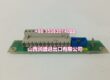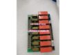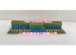
Product Core Brief
- Model: 500CMP04 / HE401314/0001 / 1MRB150051R1
- Brand: ABB
- Series: ABB DCS-Class DC Drive Systems (DCS500/DCS600)
- Core Function: Central control processor board that coordinates closed-loop speed/torque regulation, I/O management, and communications for ABB DCS-class DC drive cabinets.
- Product Type: Control Processor Board
- Key Specs: Backplane-integrated architecture | DDCS fiber communication | Supports ±10V analog loops and 24VDC digital I/O
- Condition: New Original / New Surplus
Key Technical Specifications
- Product Type: Control Processor Board
- Brand: ABB
- Model Number: 500CMP04 / HE401314/0001 / 1MRB150051R1
- Series: ABB DCS-Class DC Drive Systems (DCS500/DCS600)
- Function: Centralized control processing for speed/torque closed-loop regulation, interlock coordination, and I/O/communication management
- Power Supply: Supplied via drive backplane; typically 24VDC logic power, low consumption
- Communication Interfaces: DDCS fiber optic links as standard; RS-485/Modbus or similar via optional companion interface modules
- Signal I/O: Backplane integration with ±10V analog control loops and 24VDC digital I/O via companion boards
- Performance: Real-time deterministic processing for DC motor regulation and process line synchronization
- Mounting Method: Front-insertion plug-in card with keyed edge connectors into the drive control rack
- Operating Temperature: 0°C to +50°C (cabinet ambient, non-condensing)
- Dimensions & Weight: Board-level module, card-format size; weight typically under 0.5 kg
- Typical Applications: Metals and steel processing lines (coilers, levelers, pay-off reels); paper machines and converting lines with multi-drive sections; mining and material handling conveyors using high-torque DC motors; test benches and retrofits where DC torque responsiveness is required
Product Introduction
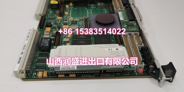
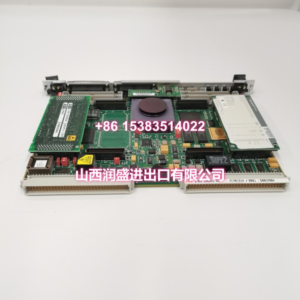
The ABB 500CMP04 (board ID HE401314/0001, order code 1MRB150051R1) is the central control processor board for ABB DCS-class DC drive systems, most commonly found in DCS500 and DCS600 installations. It serves as the “brain” of the drive controller, executing closed-loop speed and torque regulation, coordinating digital/analog I/O through the backplane, and managing communication links to upstream control systems.
This board is a critical brownfield maintenance component. When a DCS500/DCS600 drive faults due to processor failure, production lines in steel mills, paper machines, and mining conveyors can go down immediately. The 500CMP04 is a direct field-replaceable unit — no re-engineering required. Parameter sets are typically stored on the drive or can be restored from backup, making swap-out recovery fast. Its DDCS fiber communication and backplane integration with analog/digital companion boards keep it compatible with established plant architectures without forcing a full drive migration.
QA & Testing SOP
Every unit undergoes a standardized verification process before shipment:
- Visual & Anti-Counterfeit Check: Inspect the PCB for proper ABB branding, verify all three identifiers (500CMP04, HE401314/0001, 1MRB150051R1) match the label, and check for signs of previous installation such as edge connector wear, burnt components, or corrosion on the board surface.
- Backplane Seating & Communication Test: Insert the board into a compatible DCS500/DCS600 test rack and verify that the drive controller recognizes the processor correctly via the backplane bus, confirming proper firmware handshake and slot registration.
- Firmware & Parameter Integrity Check: Verify that the onboard firmware loads correctly during cold-boot. Confirm that parameter backup/restore functionality operates as expected — this is critical for field replacement scenarios where the technician needs to restore the drive’s original parameter set.
- DDCS Fiber Link Test: Verify that the DDCS fiber optic communication ports transmit and receive correctly using a loopback test or by linking to a companion DDCS module. Fiber link integrity is essential for multi-drive synchronization in process line applications.
- Analog/Digital I/O Backplane Verification: Confirm that the board correctly interfaces with ±10V analog control loops and 24VDC digital I/O signals through the backplane and companion boards, ensuring no channel faults or communication errors.
- Anti-Static Packaging: After passing all tests, the board is placed in anti-static shielding bags with desiccant packs and rigid cardboard protection for safe transit.

Installation Pitfalls & Guide
Real-World Risks When Replacing This Board:
❗ DC Bus Discharge Wait Time: Before removing or inserting the 500CMP04, isolate all power to the drive cabinet and wait for the DC bus capacitors to fully discharge. Working on a live DC drive rack risks arc flash, equipment damage, and personal injury. Always verify zero voltage at the DC bus terminals with a multimeter before proceeding.
❗ ESD Damage to Processor Components: This is a sensitive control processor board. Always wear an ESD wrist strap grounded to the cabinet frame when handling the board outside its anti-static packaging. Avoid touching component pins, edge connectors, or surface-mount ICs directly. Static discharge can cause latent failures that manifest weeks after installation.
❗ DDCS Fiber Bend Radius: When reconnecting DDCS fiber optic cables, respect the minimum bend radius (typically 30mm for standard industrial fiber). Kinking or over-bending the fiber causes signal attenuation and can lead to intermittent communication faults or complete link failure in multi-drive synchronized applications.
❗ Parameter Set Mismatch After Swap: The 500CMP04 may come with default or different firmware/parameter sets. Before returning the drive to production, verify and restore the correct parameter set for your specific application. Running a DC drive with incorrect parameters — especially current limits, speed feedback scaling, and field weakening settings — can cause motor damage or process line instability.
4-Step Replacement Guide:
- Pre-Install: Isolate all power to the drive cabinet. Wait for DC bus discharge and verify zero voltage. Document existing fiber connections, slot position, and back up the current parameter set if the old board is still partially functional.
- Removal: Disconnect all DDCS fiber cables and any front-panel connectors. Release the board retention mechanism (screws or latches), and carefully slide the old board straight out of the rack. Inspect the backplane edge connector slot for bent pins or debris.
- Install: Align the new 500CMP04 with the rack guides, ensuring the keyed edge connector matches the slot orientation. Slide the board firmly and evenly into place until fully seated. Secure retention screws/latches. Reconnect DDCS fiber cables, respecting bend radius.
- Power-On Test: Restore power and verify that the drive controller recognizes the processor. Restore the correct parameter set from backup. Run a low-speed function test with the motor uncoupled if possible, verify interlocks, and confirm DDCS communication with upstream systems before returning to production load.
Technical FAQ
Is the 500CMP04 compatible with both DCS500 and DCS600 drives? Yes, the 500CMP04 (HE401314/0001, 1MRB150051R1) is commonly used in both ABB DCS500 and DCS600 DC drive systems. However, always cross-reference the full order code against your drive’s spare parts list and firmware version before ordering. Different firmware revisions may be required for specific drive software releases.
Can I swap this board while the drive is powered (hot-swap)? No. The 500CMP04 is not designed for hot-swapping. The backplane architecture of DCS-class DC drives does not provide the isolation needed for live insertion. You must isolate all power, wait for DC bus discharge, and verify zero voltage before removing or installing the board. Hot-swapping can damage the processor, the backplane, and other connected modules.
What happens to my drive parameters when I replace this board? Parameter storage depends on your specific drive configuration. In many DCS500/DCS600 installations, parameters are stored on the drive’s non-volatile memory or on a separate memory module, not solely on the processor board. However, you should always back up the parameter set before removal if possible. After installing the new board, verify and restore the correct parameters — especially speed loop gains, current limits, field control settings, and communication addresses.
How do I know if my drive failure is caused by the 500CMP04 versus another module? DC drive faults can originate from multiple sources: power stack (thyristors), field supply, feedback devices (encoders/tachometers), or the control processor. If the drive shows no display, fails to initialize, loses communication on all channels, or exhibits erratic behavior across multiple parameters simultaneously, the processor board is a likely suspect. However, always rule out power supply issues, blown fuses, and feedback device failures first. If you have access to drive fault logs, check for processor-specific error codes.
What warranty do you offer on New Surplus parts? We provide a full 12-month warranty on all New Original / New Surplus units. This is fundamentally different from refurbished processor boards, which often carry 30–90 day warranties and come with unknown thermal cycling history, potential firmware corruption, and degraded edge connectors. For a central control processor that governs speed/torque regulation and safety interlocks, the reliability difference between new surplus and refurbished directly impacts production uptime and equipment safety.