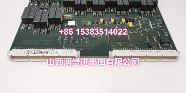
Product Core Brief
- Model: 500BOM01 / 1MRB150023R0002
- Brand: ABB
- Series: ABB AC 500 PLC Series
- Core Function: 16-channel digital output module for AC 500 PLC systems, driving control of switching signals in industrial automation systems.
- Product Type: Digital Output Module
- Key Specs: 16-channel digital output | 24VDC power supply | Group isolation
- Condition: New Original / New Surplus
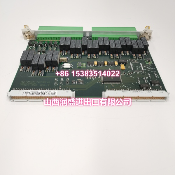
Key Technical Specifications
- Product Type: Digital Output Module
- Brand: ABB
- Model Number: 500BOM01 / 1MRB150023R0002
- Series: ABB AC 500 PLC Series
- Number of Channels: 16 digital output channels, grouped and isolated (e.g., 4 groups × 4 channels)
- Output Types: Optional transistor output (NPN/PNP) or relay output, with different versions adapting to various load requirements
- Driving Capability:
- Maximum output current per channel: 0.5A
- Maximum current per group: 4A
- Supports inductive loads (requires external flyback diode)
- Maximum power for resistive loads: 12W (24VDC)
- Power Supply: 24VDC (±20%), power consumption ≤5W
- Isolation: Electrical isolation between output channels and between channels and power supply (500V AC/1min)
- Communication Interface: Real-time communication with AC 500 CPU modules via the backplane bus
- Mounting Method: DIN rail / AC 500 rack plug-in mount
- Operating Temperature: -25°C to +60°C
- Humidity: 5% to 95% (non-condensing)
- Typical Applications: Motor start/stop control, solenoid valve driving, indicator light signal output, logic control, equipment action execution, and signal indication in industrial automation systems
Product Introduction
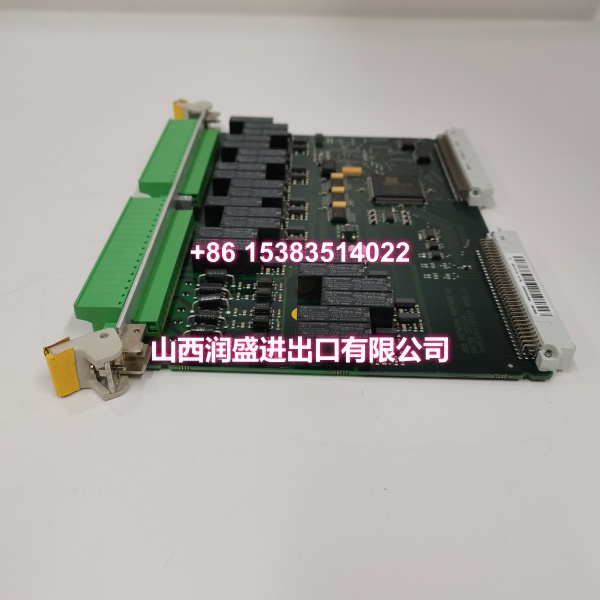
The ABB 500BOM01 (order code 1MRB150023R0002) is a 16-channel digital output module designed for ABB AC 500 PLC systems. It serves as a critical I/O interface that drives control of switching signals in industrial automation systems, enabling real-time communication with AC 500 CPU modules via the backplane bus.
This module is particularly valued in industrial automation for its reliable digital signal output and strong anti-interference capability. The 16-channel architecture supports both transistor and relay output types, accommodating a wide range of field devices. With electrical isolation between output channels and between channels and power supply, it protects the backplane and CPU from noise and voltage transients. The module is suitable for scenarios such as motor start/stop control, solenoid valve driving, and indicator light signal output in industrial automation systems.
QA & Testing SOP
Every unit undergoes a standardized verification process before shipment:
- Visual & Anti-Counterfeit Check: Inspect the PCB for proper ABB branding, verify the order code (1MRB150023R0002) matches the label, and check for signs of previous installation such as terminal wear or rack mounting marks.
- Backplane Communication Test: Insert the module into an AC 500 test rack and verify that the CPU recognizes the module correctly via the backplane bus, confirming proper firmware handshake.
- Full-Scale Channel Output Test: Cycle all 16 output channels individually, verifying correct signal presence at each terminal using a multimeter or oscilloscope. For transistor versions, confirm NPN/PNP switching; for relay versions, verify contact closure and coil operation.
- Isolation Verification: Perform a 500V AC/1min dielectric strength test between output channels and between channels and power supply to confirm galvanic isolation integrity.
- Anti-Static Packaging: After passing all tests, the module is placed in anti-static shielding bags with desiccant packs for safe transit.
Installation Pitfalls & Guide
Real-World Risks When Replacing This Module:
❗ Output Type Mismatch: The 500BOM01 comes in different versions — transistor output (NPN/PNP) and relay output. Verify your existing module’s output type before replacement. Installing a transistor version where a relay version was specified (or vice versa) can result in incompatible load driving and potential damage to field devices.
❗ Inductive Load Protection: When driving inductive loads such as solenoid valves or relay coils, external flyback diodes (for DC loads) or RC snubbers (for AC loads) must be installed at the load side. Without proper spark suppression, arcing will significantly reduce contact life and can cause output channel failure.
❗ Ground Loop Issues: Although the module provides group isolation, improper grounding of field wiring can bypass this isolation and introduce noise into the system. Ensure shielded cables are grounded at the cabinet end only (single-point grounding).
❗ Group Current Limits: Each output group has a maximum current rating of 4A. Distribute your loads evenly across groups to avoid exceeding the per-group current limit, which can cause overheating and premature module failure.
4-Step Replacement Guide:
- Pre-Install: Power down the rack or isolate the I/O section. Document existing wiring connections and take a screenshot of the slot parameters in your engineering tool (especially Safe State / Fail Position settings).
- Removal: Disconnect field wiring, release the module locking mechanism, and carefully slide the old module out of the rack. Inspect the backplane connector for bent pins.
- Install: Align the new module with the rack guides and slide it firmly into place until it locks. Reconnect field wiring according to your documented connections, verifying polarity for each channel.
- Power-On Test: Restore power and verify that the CPU recognizes the module. Force each output channel individually to confirm correct operation before returning the system to automatic mode.
Technical FAQ
What is the difference between transistor output and relay output versions? Transistor outputs (NPN/PNP) are suitable for high-frequency switching applications with response times ≤1ms, but they can only drive DC loads (typically 24VDC). Relay outputs can switch both AC and DC loads (AC 250V / DC 30V) and have stronger impact resistance, but they have slower response times (typically 10–15ms) and limited mechanical life (10⁵–10⁶ operations). Choose transistor for fast cycling applications like pulse outputs; choose relay for mixed AC/DC loads or where galvanic isolation at the contact is needed.
Can I use this module to drive high-power motors directly? No. The maximum output current per channel is 0.5A, and per group is 4A. This module is designed for driving control signals — such as starter coils, solenoid valves, and indicator lights — not for directly powering motors. For motor control, use this module to drive the coil of a contactor or motor starter, which then handles the high-current motor load.
What happens if I exceed the group current limit? Exceeding the 4A per-group current limit can cause overheating of the internal traces and output drivers, leading to premature module failure or even fire risk in extreme cases. Always calculate the total current draw of all channels within a group and ensure it stays within the 4A limit. Distribute high-current loads across different groups when possible.
Do I need external protection for inductive loads? Yes, absolutely. When switching inductive loads (solenoid valves, relay coils, contactor coils), you must install external flyback diodes for DC loads or RC snubber circuits for AC loads at the load side. Without this protection, the back-EMF generated when the inductive load is de-energized can cause arcing across the output contacts (relay version) or voltage spikes that damage the output transistors (transistor version).
What warranty do you offer on New Surplus parts? We provide a full 12-month warranty on all New Original / New Surplus units. This is fundamentally different from refurbished I/O modules, which often carry 30–90 day warranties and come with unknown thermal cycling history, degraded output drivers, and potential terminal wear. For digital output modules where reliable signal delivery is critical to process control and safety interlocks, the reliability difference between new surplus and refurbished is significant.