Product Quick-Glance Brief
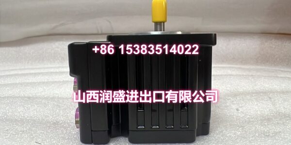
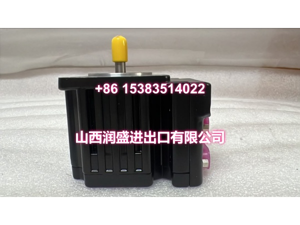
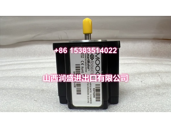
- Model: MOOG D661-4651
- OEM: MOOG
- Category: Two-Stage ServoJet Servo Valve
- Core Function: Delivers high-precision flow control with integrated electronics and LVDT feedback for closed-loop industrial applications.
- Key Specs: 350 bar Max Pressure, ISO 4401-05 (NG10), ServoJet Pilot
Technical Overview & Field Application
Contamination is the silent killer of hydraulic precision. Traditional nozzle-flapper pilots clog and drift. The MOOG sidesteps this problem entirely with its ServoJet pilot stage. No tiny orifices to plug. Just a robust jet pipe that tolerates real-world oil conditions while maintaining tight control.
This valve integrates the amplifier and LVDT feedback directly into the housing. You get true closed-loop spool positioning without external cards. The electronics accept standard ±10 V or 4-20 mA commands and internally correct for hysteresis and pressure shifts. Hysteresis stays below 0.5%. That’s the difference between consistent part quality and scrap.
Field teams rely on its millisecond-class response. Step times hit 6.5–14 ms depending on system pressure. Whether you’re controlling injection velocity in molding or roller gap in steel rolling, the valve tracks commands without lag. The spring-center fail-safe option also ensures the spool returns to mid-position on power loss, protecting your tooling and workpiece.
Essential Specifications
| Parameter | Specification |
|---|---|
| Pilot Type | ServoJet (Jet Pipe) |
| Max Operating Pressure | 350 bar (P, A, B Ports) |
| Rated Flow | 20–200 L/min @ Δp 35 bar |
| Response Time | 6.5–14 ms (Step @ 210 bar) |
| Feedback | Integrated LVDT (Valve-In-The-Loop) |
| Control Signal | ±10 V / ±10 mA / 4–20 mA |
| Mounting Interface | ISO 4401-05 (NG10) |
| Hysteresis | < 0.5% |
| Oil Cleanliness | NAS 6–7 Recommended |
| Fail-Safe | Spring Center (Optional) |
Quality Assurance Protocol
Every MOOG is validated against OEM performance baselines. We don’t ship valves that “mostly” work.
- ServoJet Pilot Flow Check: We verify pilot stage flow symmetry to confirm the jet pipe isn’t worn or misaligned. Asymmetry causes null shift under pressure.
- LVDT Linearity Sweep: Spool position feedback is mapped across full stroke. Non-linearity >0.5% triggers rejection.
- Dynamic Step Response: Rise time and settling are measured at 210 bar system pressure. Sluggish response indicates spool drag or degraded coil.
- Integrated Electronics Burn-In: The onboard amplifier runs at max current for 4 hours to catch early-life capacitor or MOSFET failures.
Note: Units with hysteresis >0.5% are quarantined. In servo applications, hysteresis compounds over cycle time and destroys repeatability.
Engineer’s Installation / Replacement Notes
Verify the full model string before installing. The “G35JOAA6VSX2HA” suffix defines flow rating, spool type, seal material, and fail-safe behavior. A mismatch here means incorrect flow or seal failure at 350 bar.
- Oil Cleanliness is Non-Negotiable: ServoJet is tolerant, not invincible. Target NAS 6–7 (ISO 4406 15/12 or better). Flush lines thoroughly if replacing a failed valve; debris from the old failure will kill the new one.
- Ground the Shield Correctly: The LVDT signal is low-level. Ground the cable shield at the controller end only. Grounding at both ends creates a ground loop that looks like spool oscillation.
- Check Return Line Pressure: If T-port backpressure exceeds 210 bar, use an external drain. High return pressure shifts the spool and destroys control accuracy.
- Zero Trim via Controller: If you see null drift, use electronic zero adjustment through your PLC or motion controller. Mechanical stops on integrated valves are a last resort and often void calibration.
- Warm-Up Before Full Load: After installation, run the system at low pressure for 10–15 minutes. This seats seals and brings oil to operating temperature before applying full 350 bar load.