
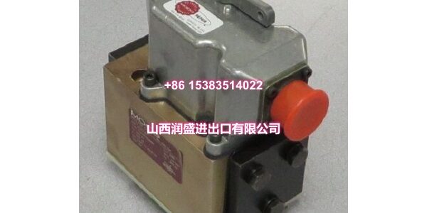
Product Quick-Glance Brief
- Model: MOOG D662-4709
- OEM: MOOG
- Category: Servo-Proportional Control Valve (D660 Series)
- Core Function: Delivers high-dynamic flow control with integrated 24 VDC electronics and ServoJet® pilot stage.
- Key Specs: ISO 4401 Size 05, 350 bar Max Pressure, Integrated SMD Amplifier
Technical Overview & Field Application
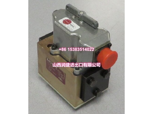
Energy waste and heat generation are the hidden costs of traditional servo valves. The MOOG attacks this problem at the source. It belongs to the D660 series, featuring a ServoJet® pilot stage that drastically reduces pilot flow losses compared to conventional nozzle-flapper designs. This isn’t just about efficiency; it’s about thermal stability in your hydraulic cabinet. Less heat means longer fluid life and more consistent performance during continuous operation.
This unit is a true servo-proportional valve with integrated 24 VDC electronics. You can eliminate external amplifier cards, reducing panel space and wiring complexity. The internal SMD circuitry provides closed-loop control via an LVDT, ensuring high resolution and low hysteresis without the tuning headaches of analog cards. With a maximum operating pressure of 350 bar and dynamic response suitable for position, velocity, and force control, it’s engineered for demanding applications like metal forming, injection molding, and precision test stands.
Global deployment requires standardized interfaces. The MOOG conforms to the ISO 4401-05 (NG10) mounting pattern, ensuring direct interchangeability with legacy systems worldwide. The “4709” suffix defines specific performance characteristics, including spool type, seal material, and electrical options. Always verify the full suffix when replacing a failed unit, as even minor variations can affect system stability or safety functions.
Essential Specifications
| Parameter | Specification |
|---|---|
| Valve Type | Servo-Proportional Control Valve (D660 Series) |
| Mounting Pattern | ISO 4401-05-05-0-05 (NG10) |
| Max Operating Pressure | 350 bar (5,000 psi) at P, A, B ports |
| Rated Flow | 20 to 200 L/min @ 35 bar drop per land |
| Max Flow | 250 L/min |
| Step Response (0-100%) | 6.5 to 18 ms |
| Supply Voltage | 24 VDC (18 to 32 VDC range) |
| Signal Options | ±10 V, ±10 mA, 4-20 mA |
| Pilot Stage | ServoJet® Pilot Valve |
| Fail-Safe Function | Spring Centered on Power Loss |
Quality Assurance Protocol
We verify dynamic performance, not just part numbers. Every MOOG undergoes rigorous functional testing to ensure the integrated electronics and ServoJet® pilot stage meet OEM specifications. We test the entire closed-loop system.
- ServoJet® Pilot Verification: We validate the pilot stage’s dynamic response and centering accuracy to ensure optimal main spool control.
- Step Response Testing: We apply a 100% step signal to confirm the valve achieves its target position within the 6.5-18 ms threshold.
- Integrated Amplifier Check: The internal SMD electronics are tested for correct gain, offset, and PWM drive to the torque motor.
- Leakage & Pressure Test: Each valve is cycled at 350 bar to validate seal integrity and internal leakage rates.
Pro Tip: Always verify the control signal type (voltage vs. current) matches your PLC or motion controller output before wiring. A mismatched signal will cause the integrated amplifier to fault or behave erratically.
Engineer’s Installation / Replacement Notes
Field installation of a ServoJet® valve is straightforward, but fluid cleanliness and electrical noise remain critical. Follow these peer-to-peer guidelines to protect your investment.
- Fluid Cleanliness is Non-Negotiable: While ServoJet® pilots are more tolerant than nozzle-flappers, they still demand clean fluid. Target ISO 4406 <15/12 to protect the main spool lands and prevent premature wear.
- Signal Shielding: The integrated amplifier processes low-level signals. Route the control cable away from VFDs and high-current motor leads. Always ground the shield at the controller end to prevent electromagnetic interference.
- T Port Pressure Limits: If your T (tank) port pressure exceeds 210 bar with internal drain, you must use the Y port for external drain. Ignoring this can blow out the internal shaft seals.
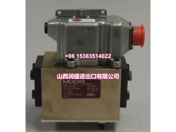
- Verify the “4709” Suffix: The suffix defines critical options. Is it a zero-overlap or positive-overlap spool? Does it have a fail-safe spring? Mismatched suffixes will cause system failure or safety hazards.
Critical Warning: Never apply 24 VDC to the signal input terminals. The integrated amplifier expects a low-power command signal. Reversing power and signal wiring will instantly destroy the internal SMD electronics.




