Product Quick-Glance Brief
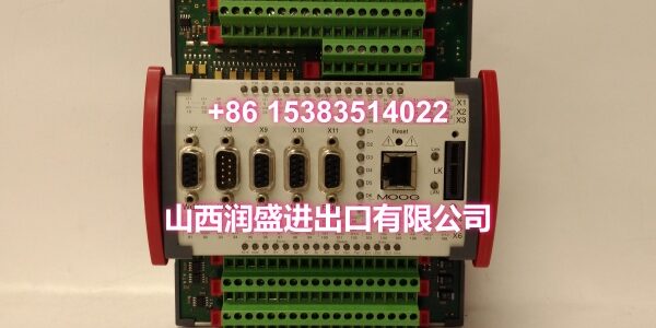
- Model: MOOG D138-002-012
- OEM: MOOG
- Category: Intelligent Servo Controller / Motion Module
- Core Function: Provides precise, closed-loop motion control with integrated PLC logic for demanding hydraulic and electric applications.
- Key Specs: 24 VDC Nominal, ±10 V Analog I/O, DIN-Rail Mount
Technical Overview & Field Application
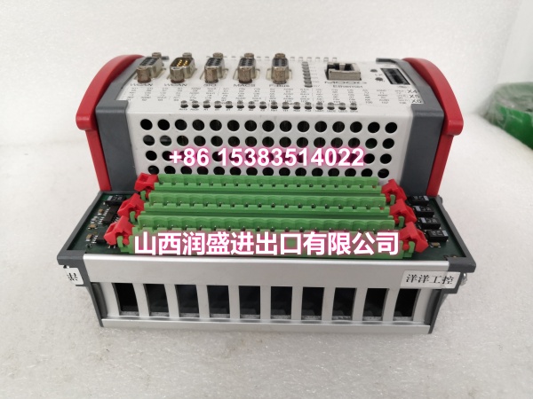
Cabinet space is always a premium. You need high-performance motion control, but you don’t have room for a stack of separate drives and PLCs. The MOOG solves this by packing intelligent servo control into a compact DIN-rail footprint.
This isn’t just a dumb amplifier. It’s a full motion controller with embedded logic. You get fast, stable control tuned specifically for the dynamic demands of test rigs and press applications. The unit handles ±10 V analog I/O and 24 VDC digital signals natively, making integration with your existing sensors and valves straightforward.
Diagnostics shouldn’t be a guessing game. This module features status LEDs and supports software tools that speed up commissioning. Whether you’re using Ethernet for configuration or CANopen for real-time fieldbus control, the hardware is built to keep your machine running and your troubleshooting time short.
Essential Specifications
| Parameter | Specification |
|---|---|
| Power Supply | 24 VDC Nominal (18–32 VDC) |
| Power Consumption | ≈ 10–15 W (Typical) |
| Analog I/O | ±10 V / 4–20 mA |
| Digital I/O | 24 VDC DI/DO |
| Communication | Ethernet, CANopen, RS-485/Modbus RTU |
| Mounting | DIN-Rail (EN 60715) |
| Dimensions | Approx. 120 × 50 × 115 mm |
| Weight | ~0.6 kg |
| Operating Temp | 0 to +55 °C |
| Protection | IP20 (Panel Mounted) |
Quality Assurance Protocol
We treat every MOOG D138-002-012 as a mission-critical component. Our validation process is clinical and transparent.
- Power Rail Verification: We stress-test the internal 24 VDC regulation under full I/O load to ensure no voltage sag during peak motion commands.
- Signal Linearity Check: Analog inputs and outputs are swept to verify ±10 V accuracy and 4–20 mA scaling across the entire range.
- Bus Integrity Test: Ethernet and CANopen ports are exercised with high-traffic packets to confirm zero dropouts and correct node ID assignment.
- Thermal Validation: Units are run at max load within the 0–55 °C operating window to verify heat dissipation and component stability.
Note: Any unit failing the bus integrity test is flagged for connector or PHY-level inspection. We don’t ship modules with intermittent communication.
Engineer’s Installation / Replacement Notes
Verify your license key before installation. The D138 series often requires a specific passcode dongle (like D138-002-002) to unlock motion libraries or fieldbus features. Don’t get stuck on the bench.
- DIN-Rail Grounding: The compact footprint means less surface area for heat sinking. Ensure your DIN rail is properly grounded to the cabinet chassis to aid thermal dissipation and EMI rejection.
- Wiring Separation: Keep your ±10 V analog signal cables physically separated from the 24 VDC power and digital I/O lines. Induced noise here looks like sensor drift, and you’ll waste hours chasing ghosts.
- EtherCAT Option: If your deployment uses EtherCAT, confirm the specific hardware revision. Not all D138-002-012 units have the EtherCAT PHY populated; some are configured for standard Ethernet/TCP/IP only.
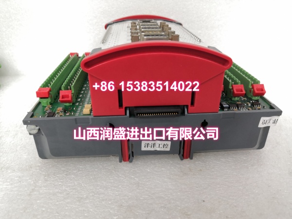
- Front Connectors: The pluggable front connectors are convenient but fragile. Always use the correct torque on the terminal screws. A loose connection under vibration will cause intermittent faults that are nearly impossible to diagnose in the field.