Product Core Brief
- Model: RS-FS-9001 (362A1052P004)
- Brand: GE (Reuter-Stokes, Baker Hughes division)
- Series: Flame Tracker SiC UV Flame Detection Transmitter Series
- Core Function: Detect UV radiation from combustion flames, convert flame intensity to standard 4–20 mA two-wire signal for turbine protection relays and DCS input modules
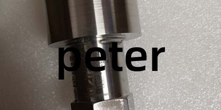
- Product Type: Threaded stainless steel industrial flame detector probe
- Key Specs: Silicon Carbide UV photodiode | Sapphire optics window | 4–20 mA flame proportional output | 12–30 V DC two-wire loop power ⚠️ EOL — limited stock remaining
Product Introduction
GE RS-FS-9001 uses a silicon carbide UV photodiode to capture flame UV emissions from gas turbine, boiler, and burner combustion zones, outputting a continuous 4–20 mA analog signal proportional to flame intensity for host protection relays like SR489 generator relays. This unit differs from the RS-FS-9006 aviation variant by removing aerospace certification and optimizing the optical path for industrial power plant combustion environments. It delivers full signal response within 25 ms and maintains stable measurement output across -40 °C to +150 °C process ambient bands, with water cooling available to extend probe tip temperature to 235 °C.
Key Technical Specifications
| Parameter | Value |
|---|---|
| Flame sensing element | Silicon Carbide (SiC) UV photodiode, 310 nm peak sensitivity |
| Optical window material | Sapphire scratch/heat resistant lens |
| Standard signal output range | 4–20 mA two-wire proportional flame intensity |
| Flame detection threshold | >5 mA at 1×10¹⁰ photons/in²/sec UV flux |
| Maximum short-circuit loop current | 7.9 mA DC |
| Full signal response time | ≤25 ms flame presence/absence detection |
| Auxiliary loop supply voltage | 12 V DC to 30 V DC SELV, minimum 100 mA drive capacity |
| Process pressure rating | 400 psig (2.8 MPa) continuous service |
| Uncooled probe operating temperature | -40 °C to +150 °C |
| Water-cooled maximum tip temperature | 235 °C continuous (requires OEM cooling accessory) |
| Mechanical process connection | 3/4” NPT female threaded mounting base |
| Electrical connector | MIL-C-38999 Series III size 15, 5-pin circular plug |
| Vibration tolerance | 8 G continuous 40–2000 Hz; 14 G peak shock rating |
| Maximum field cable length | 100 m shielded twisted pair (max loop resistance 560 Ω at 24 V DC) |
| Housing construction | AISI 316 stainless steel wetted surfaces |
| Compliance standards | ATEX IIC, IECEx, NFPA 85/87, CE industrial certification |
Quality Control Process (Engineer’s Perspective)
- Incoming Verification: Cross-reference serial numbers against GE Reuter-Stokes flame detection spare asset database to flag counterfeit hardware. Inspect MIL circular connector pins and sapphire optical window with a 10x magnifier for scratches or oxidation; log serial numbers for gas turbine plant traceability.
- Live Functional Test: Power the unit via a 24 V DC supply paired with an SR489 generator relay analog input channel. Simulate UV flame flux across full 4–20 mA output span, run continuous 26-hour load testing while logging cabinet temperature shifts and 4–20 mA output linearity drift.
- Electrical Parameter Test: Use a 500 V Megger to measure insulation resistance between signal wiring terminals and stainless steel probe housing; pass threshold set at >10 MΩ. Verify protective ground loop resistance below 0.5 Ω with a Fluke 115 multimeter.
- Firmware Verification: This analog flame transmitter uses passive SiC photodiode conditioning circuits with no programmable onboard firmware. Photograph circular connector pin polarity labels printed on the probe housing for field wiring reference.
- Final QC & Packaging: Wipe stainless steel probe body with anti-static microfiber cloth, cap the MIL electrical connector with plastic dust covers. Seal inside a static-shielding transport bag, attach a QC Passed label stamped with full test completion date.
Replacement Pitfall Guide
❗ Firmware Mismatch: The unit contains no onboard firmware, but host SR489 generator relay firmware v5.2 and older lack linear 4–20 mA flame intensity scaling logic. Match exact relay firmware builds before power-up, or flame readings lock at fixed 4 mA (no-flame) permanently. ❗ DIP Switch / Jumper Misconfiguration: Factory default analog input scaling jumper on SR489 relays is set for 0–20 mA transducer signals. Flame detection loops require 4–20 mA offset scaling enabled; missed jumper adjustment hides weak flame intensity during low-load turbine operation. ❗ Terminal / Cable Incompatibility: This unit uses 5-pin MIL circular field connectors, unlike low-signal UR8LH 1.5 mm spring terminal I/O modules. Unshielded twisted pair cabling routed alongside high-current CT wiring creates noisy flame signal drift; shield drain wires must land on dedicated protective ground bars only. ❗ Power Supply Mismatch: Full flame detection loop draws 100 mA peak DC current. Calculate rack power budget with 20 % overhead; undersized URRHH 24 V DC power supplies trigger low-voltage lockout and missing flame status alarms. ❗ ESD Damage: Dry cabinet environments above 40 % relative static risk degrade internal signal conditioning resistors on the unit. Always use an anti-static mat and grounded wrist strap when handling exposed MIL connector pins and optical window surfaces. Keep these in mind and you’ll cut 90% of rework time.
Compatibility Matrix & Benchmarks
Compatibility Matrix
- RS-FS-9006 → RS-FS-9001 362A1052P0004 : Needs Adaptation — RS-FS-9006 carries aviation certification, identical 4–20 mA output wiring
- SR489 Generator Protection Relay → RS-FS-9001 362A1052P0004 : Direct — compatible with A20 analog output input channels, adjust scaling for 4–20 mA flame span
- UR8LH Analog Input Module → RS-FS-9001 362A1052P0004 : Direct — accepts standard 4–20 mA two-wire transmitter signals without circuit modification
- VMIVME-7807 VME SBC → RS-FS-9001 362A1052P0004 : Incompatible — separate VME64 backplane architecture, no native analog loop input mapping