
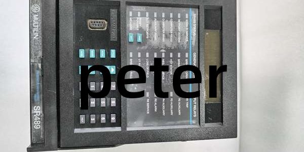
Product Core Brief
- Model: SR489-P1-HI-A20-E-H
- Brand: GE (Multilin / GE Vernova)
- Series: SR489 Synchronous Generator Protection & Control Platform
- Core Function: Multi-function digital generator relay with high-impedance ground fault protection, cold-temperature rated and fully conformal coated for marine/mining harsh environments
- Product Type: Drawout 5U vertical panel-mount generator protection relay
- Key Specs: P1=1 A CT secondary inputs | HI=70–265 V AC / 90–300 V DC wide auxiliary feed | A20=4 galvanically isolated 4–20 mA outputs | H=Full PCB conformal coating for harsh environments ⚠️ EOL — limited stock remaining
Product Introduction
E samples PT voltage and 1 A CT secondary signals, executes 30 programmable ANSI protection algorithms, and converts operational metrics to isolated analog signals for plant DCS systems. It integrates 12-channel RTD thermal monitoring for stator and bearing temperature supervision without external I/O modules. This unit differR489-P1-HI-A20-E by adding full PCB conformal coating for humidity, dust, and chemical resistance, plus extended cold-start capability down to -40 °C. It holds ±0.5 % steady-state metering accuracy across -40 °C to +60 °C cabinet bands, stores 256 timestamped fault events, and captures oscillography waveforms at 12 samples per cycle during fault transients.
Key Technical Specifications
| Parameter | Value |
|---|---|
| Secondary CT rated input | 1 A AC phase current (P1 suffix configuration) |
| Auxiliary supply voltage range | 70–265 V AC 48–62 Hz; 90–300 V DC wide-range feed (HI suffix) |
| Supported generator frequency | 25 Hz, 50 Hz, 60 Hz user-selectable |
| Isolated analog outputs | 4x 4–20 mA (A20 suffix), software-scalable 0–20 mA range |
| RTD temperature input capacity | 12 PT100 / PT1000 stator & bearing thermal loops |
| Binary digital input allocation | 8 dry-contact breaker/disconnect status inputs |
| Relay output allocation | 6 independent Form-C SPDT trip/alarm contacts |
| Core native protection elements | High Impedance Ground Fault, Harmonic Restraint, Over/Undervoltage, Reverse Power, Overcurrent, Loss of Excitation |
| Fault event storage capacity | 256 timestamped sequence-of-events trip logs |
| Oscillography buffer capacity | 128 cycle waveform capture at 12 samples per cycle |
| Harsh environment feature | Full PCB conformal coating (H suffix) for marine/mining corrosive atmospheres |
| Communication ports | Dual rear RS485 (Modbus RTU / DNP3.0), front RS232 local service |
| Operating cabinet temperature | -40 °C to +60 °C sealed IP20 enclosure |
| Storage temperature range | -40 °C to +85 °C |
| Mechanical form factor | Standard 5U vertical drawout panel cutout housing |
| Net unit weight | 7.7 kg |
| Compliance standards | IEC 61003-0, IEC 61000-6-2, IEEE C37.102, CE, DNV marine certified |
Quality Control Process (Engineer’s Perspective)
- Incoming Verification: Cross-reference serial numbers against GE Multilin generator protection spare database to flag counterfeit hardware. Inspect CT/PT terminal blocks, dual RS485 ports, and front backlit LCD HMI with a 10x magnifier for oxidation or cracked PCB traces; log serial numbers for marine/mining power plant traceability.
- Live Functional Test: Mount the unit on a panel test rack paired with a SR series test CPU and variable AC voltage/current simulators. Inject full-range PT and 1 A CT signals, run continuous 26-hour load testing while logging cabinet temperature shifts and measuring protection element pickup timing deviation.
- Electrical Parameter Test: Use a 500 V Megger to measure insulation resistance between CT/PT high-potential terminals and chassis ground; pass threshold set at >10 MΩ. Verify PE protective ground loop resistance below 0.5 Ω with a Fluke 115 multimeter.
- Firmware Verification: Extract and record internal DSP protection firmware revision printed on PCB silkscreen. Photograph RS485 bus termination jumper and RTD input polarity labels for field commissioning reference.
- Final QC & Packaging: Wipe front HMI and metal drawout housing with anti-static microfiber cloth, cap all signal and communication terminal blocks with plastic dust covers. Seal inside a shielding ESD bag, attach a QC Passed label stamped with full test completion date.
Replacement Pitfall Guide
❗ Firmware Mismatch: firmware v5.4 drops backward compatibility with legacy Enervista 489PC software v3.0 and older builds. Match exact firmware revisions before rack power-up, or high-impedance ground fault protection will fail to detect winding faults indefinitely. ❗ DIP Switch / Jumper Misconfiguration: Factory default RS485 bus termination resistor is disabled. Most multi-generator substation SCADA trunks require the resistor enabled on the last relay in the communication chain; missed settings create cyclic Modbus RTU packet loss under peak generator full-load operation. ❗ Terminal / Cable Incompatibility: This unit uses 2.5 mm spring CT/PT power terminals, unlike low-signal UR8LH 1.5 mm transducer blocks. Oversized wire strands create loose CT wiring and intermittent metering dropout; always short CT secondary terminals before disconnecting field wiring per GE service manual. Shield drain wires must land on dedicated protective ground bars only. ❗ Power Supply Mismatch: Full 4 analog output + 6 relay contact peak load draws 40 W auxiliary power. Calculate rack power budget with 20 % overhead; undersized URRHH DC power supplies trigger under-voltage lockout and blank HMI metering displays. ❗ ESD Damage: Dry cabinet environments above 40 % relative static risk degrade internal DSP and analog output driver chips on the unit. Always use an anti-static mat and grounded wrist strap when accessing rear terminal wiring and exposed PCB layers. Keep these in mind and you’ll cut 90% of rework time.
Compatibility Matrix & Benchmarks
Compatibility Matrix
- → : Needs Adaptation — base E model lacks conformal coating, cold temperature operation limited to -20 °C
- S→ : Needs Adaptation — P5 uses 5 A CT inputs, current scaling parameters must be reconfigured
- Multilin 889→ : Direct — identical panel cutout dimensions, minor analog output scaling adjustment required
- UR9H→ : Incompatible — separate UR series proprietary backplane architecture, no shared signal bus mapping




