
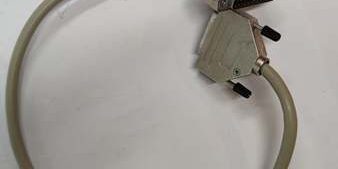
Product Core Brief
- Model: TK801V006, OEM Article Number 3BSC950089R2
- Brand: ABB
- Series: S800 I/O ModuleBus accessory cable for AC800M / 800xA DCS
- Core Function: Links TB806 inlet adapters across separate DIN rails to extend ModuleBus communication within a single cabinet
- Product Type: Prefabricated shielded ModuleBus extension cable
- Key Specs: 0.6m fixed length | D-Sub25 male-female connectors | Full aluminum + copper braid shielding
- Note: Active OEM spare production; factory sealed new assemblies and fully continuity-tested surplus available for plant I/O cabinet layout retrofits
Key Technical Specifications
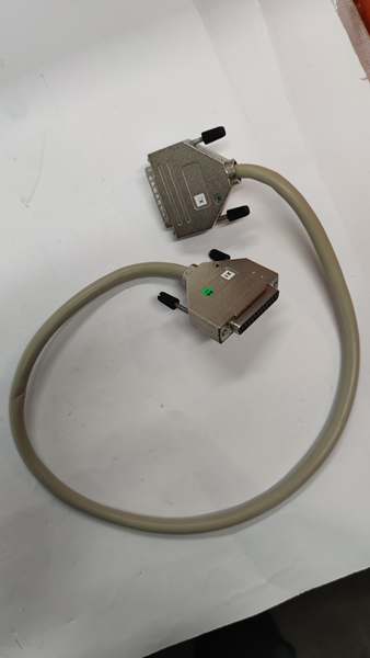
- Total cable length: 600 mm (0.6 m)
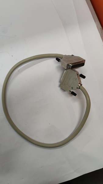
- Connector configuration: 25-pin male D-Sub on one end, 25-pin female D-Sub on opposite end
- Shield construction: Dual-layer aluminum foil inner shield + tinned copper braid outer shield
- Conductor type: Twisted pair matched to ModuleBus differential impedance requirements
- Max combined extension limit: Total cumulative TK801 cable runs cannot exceed 2.5m per bus segment
- Operating ambient temperature: -20°C to +70°C inside sealed cabinet enclosures
- Storage temperature range: -40°C to +85°C
- Humidity rating: 5%–95% RH non-condensing below 55°C
- Minimum bending radius: 8x outer cable diameter to avoid conductor breakage
- Net assembly weight: 0.19 kg
- Compliance: EU RoHS 2011/65/EU, IEC 61000-6-2 industrial EMC standard
- Compatible hardware: TB805, TB806, TB845, TB846 ModuleBus inlet adapters
Product Introduction
This prefabricated cord bridges ModuleBus signals between I/O clusters mounted on separate DIN rails, eliminating custom field wiring that introduces impedance mismatches and EMI noise. Its factory-calibrated twisted pair layout maintains consistent bus scan timing below 250ms, and dual-layer shielding blocks transient interference from nearby MCC motor starters and variable frequency drives.
QA & Testing SOP (Transparency Building)
- Incoming Inspection: Cross-reference serial number against ABB S800 spare asset database to filter counterfeit cables; inspect D-Sub25 pin contacts, cable outer jacket and shield termination with a 10x magnifier for bent pins or jacket cracking; log serial numbers for full I/O system traceability records.
- Live Testing: Mate the cable between two TB806 adapters on a multi-rail test bench paired with a CI810 communication module; run a continuous 24-hour cycle test including full I/O point scanning and transient EMI injection to validate zero packet loss across the bus segment.
- Electrical Testing: Use a Fluke 115 multimeter to perform full continuity checks across all 25 pin pairs; verify shield continuity from male to female connector shell to confirm unbroken noise suppression paths.
- Firmware/Config Backup: Photograph original cable routing layout and OEM maximum total extension length limits for site wiring reference.
- Final QC & Packaging: Wipe cable jacket with static-dissipative microfiber cloth; cap both D-Sub connectors with insulating plastic dust covers; bundle the cable with a static-free tie, attach a printed QC tag with full 24-hour bus communication test timestamp, then pack into foam lined transit cartons.
Installation Pitfalls & Guide (Engineer to Engineer)
❗ Exceeding total 2.5m cumulative cable length creates scan timeouts: Stacking multiple cords pushes bus cycle timing above 500ms, breaking closed-loop control scan window requirements. ❗ Unsecured cable routing pinches internal twisted pairs: Sharp cabinet edges cut shielding layers, leading to constant Modbus retries and intermittent I/O dropout. ❗ Missing D-Sub lock screws create intermittent contact loss: Vibration from cooling fans loosens unfastened connectors during long-term continuous plant operation. ❗ ESD discharge damages adjacent terminal base logic: Unwrapped cable handling without a grounded wrist strap transfers static charge to TB806 PCB signal traces, requiring full I/O rack power cycling to restore communication. ❗ Hot-swapping live ModuleBus connectors generates bus parity faults: Unplugging the cord while the rack remains energized corrupts differential bus clock signals and forces the host CI8xx controller to cold restart.
4-step replacement guide
- Pre-install: Lock out and tag cabinet 24VDC auxiliary power supply; wait 10 minutes for internal rack capacitors to fully discharge; don ESD wrist strap; capture photos of male/female D-Sub connector pairing and original cable routing path.
- Removal: Unthread D-Sub lock screws on both ends one at a time; pull the old cable straight out without bending connector pins or pulling tight on the cable jacket.
- Install: Route the new cord matching the photographed path; seat male and female D-Sub connectors fully into the TB806 ports, torque lock screws to OEM specified values to maintain solid shield contact.
- Power-on Test: Restore rack 24VDC power; confirm CI810 BUS LED shows steady green status; trigger full analog/digital I/O scan to verify all process values upload to the DCS HMI without missing data frames.

FAQ
Q: Can this cord be mixed with TK801V012 1.2m extension cables on the same bus segment? A: It can be paired, but sum of all extension cable lengths must stay below the 2.5m maximum total limit. Exceeding this threshold degrades bus signal integrity and triggers recurring communication fault alarms. Q: Is hot-swapping supported while rack 24VDC auxiliary power remains energized? A: It is not supported. The live ModuleBus differential signal lines carry high-speed clock data; unplugging the cable creates voltage transients that disrupt bus framing and drop all connected I/O channels offline, creating plant monitoring blind zones. Full power lockout and capacitor discharge wait time are mandatory. Q: What warranty coverage applies to stocked units? A: Factory-new original prefabricated bus cables carry a 12-month OEM warranty covering twisted pair conductors, D-Sub pin contacts and dual-layer shielding assemblies. Continuity-tested surplus units come with a 6-month functional warranty. Damage from over-bending, unfastened connector lock screws or ungrounded ESD handling voids all coverage. Q: What cord variant replaces this unit for wider cabinet rail spacing? A: The TK801V012 1.2m variant is the direct longer drop-in replacement for multi-rail layouts with increased separation between I/O clusters. The 0.6m length is reserved for standard compact cabinet rail spacing only. Q: Will existing bus configuration parameters shift after swapping this cable? A: All bus timing and impedance characteristics are passive hardware properties; swapping a matching cord does not alter controller scan settings or stored I/O logic. No manual reconfiguration is required post-replacement beyond verifying physical connector seating. Q: What are the most common failure modes for a faulty cord? A: Broken internal twisted pair conductors from over-bending, incomplete shield continuity causing constant EMI-induced packet loss, bent D-Sub pins that create intermittent channel dropout, loose connector shell contact that triggers random bus fault alarms, and outer jacket abrasion exposing internal wiring to cabinet ground shorts.




