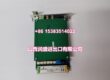
Product Core Brief
- Model: DSBC176, OEM part number 3BSE019216R1; assembly kit variant DSBC176K01
- Brand: ABB
- Series: S100 rack bus extender hardware for Advant Mod300 legacy DCS systems
- Core Function: Repeat and extend the S100 ModuleBus signal to connect multiple separate I/O subracks within a 12-meter cable limit
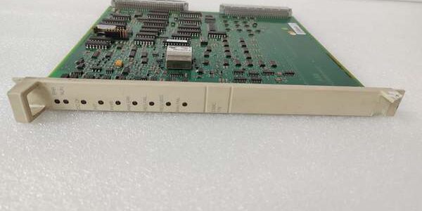
- Product Type: Standard Eurocard slide-in S100 rack passive bus repeater PCB, paired with TK575/TK580 extension cables
- Key Specs: 12m maximum inter-rack cable length | Passive signal regeneration | No user firmware required | 24VDC rack logic powerNote: Discontinued legacy bus coupler, stocked inventory is New Surplus with intact factory anti-static packaging.
Key Technical Specifications
- Auxiliary operating supply: 24VDC ±20% rack logic feed, typical power draw 90mA
- Bus type: S100 internal ModuleBus for Mod300 I/O subracks
- Maximum extension distance: 12 meters total between paired units using approved TK-series shielded cables
- Operating bus speed: Native backplane synchronous clock rate, no speed reduction across extender
- Circuit topology: Passive signal buffering with differential line drivers to suppress crosstalk
- Galvanic isolation: 500VAC separation between local rack backplane and extension cable bus ports
- Integrated protection: EMC transient surge clamping on both rack-side and cable-side bus terminals, reverse 24VDC supply blocking
- Continuous operating temperature: 0°C to +55°C full bus load; linear performance derate above 55°C
- Storage environmental limits: -40°C to +85°C, 5%–95% RH non-condensing
- Physical dimensions: 324mm D × 22.5mm W × 234mm H; unit mass 0.40kg
- Enclosure rating: IP20, for installation inside closed control cabinets only
- Compliance standards: CE, UL, IEC 61000-6-2 Class A industrial EMC
- System compatibility: Advant Mod300 AC410/AC460 controllers, AC800M via CI856 interface; incompatible with S800, UNITROL, S400 DSAX452 remote I/O platforms
Product Introduction
This bus repeater regenerates ModuleBus clock and data signals to link multiple independent I/O subracks without signal attenuation over short cross-cabinet cable runs. It operates as a transparent passive coupler requiring zero DCS software configuration after physical wiring.Differential line drive circuitry mitigates EMI noise from nearby AC motor and contactor wiring, eliminating intermittent I/O point dropouts common on unbuffered extended bus runs in refinery and power plant cabinets.
QA & Testing SOP (Transparency Building)
- Incoming Inspection: Cross-reference serial numbers against ABB Mod300 legacy component trace databases; inspect backplane gold edge fingers for oxidation, bus connector pin integrity, PCB conformal coating for peeling; verify factory static packaging seal remains unbroken for surplus inventory.
- Live Testing: Mount the unit to dual linked rack test benches paired with an AC460 controller simulator and full mixed AI/AO/DI/DO I/O load banks; run uninterrupted 24-hour cyclic bus polling across the full 12m cable distance limit; use a Fluke 115 to log steady 24VDC auxiliary supply voltage through the full test cycle.
- Electrical Testing: Perform 500VAC hipot insulation testing between local rack bus contacts and extension cable bus terminals; pass threshold set at >10MΩ insulation resistance; inject reversed DC supply voltage to confirm hardware polarity lockout activates without damaging differential driver semiconductors.
- Firmware/Config Backup: No onboard programmable firmware or parameter storage; photograph bus extension cable pin assignments to document standard inter-rack wiring layouts for site commissioning reference.
- Final QC & Packaging: Torque all bus cable connector screw terminals to OEM torque values; enclose the board in static-dissipative foam; attach a printed QC tag listing serial number and completed test metrics before carton sealing.
Installation Pitfalls & Guide (Engineer to Engineer)
❗Cable Length Overrange Risk: Installing extension cabling longer than the 12m rated maximum causes clock signal distortion and intermittent loss of entire remote subrack I/O data. Fault outcome: Random analog/digital point timeouts, untriggered process interlock alarms. Mitigation: Measure total cable length before routing; use TC560 optical modems for runs exceeding 12m.❗Platform Incompatibility Risk: Attempting to install the unit into S800 or UNITROL racks creates mismatched backplane pinouts and unsupported bus protocol logic. Fault outcome: No ModuleBus communication, burned differential driver circuits, permanent unit failure. Mitigation: Only deploy the coupler within dedicated Mod300 rack architectures paired with TK575/TK580 extension cables.❗Missing Bus Termination Risk: Failing to install DSTC176 terminator units on the final subrack bus port creates signal reflection noise. Fault outcome: Fluctuating analog readings and inconsistent discrete status polling during peak bus traffic. Mitigation: Fit OEM termination resistors at both physical endpoints of the extended bus trunk per wiring schematics.❗Mixed Power & Signal Wiring Error: Routing high-current AC power cables parallel to unshielded extension cabling induces heavy EMI interference. Fault outcome: Cyclic bus communication fault counters that spike during pump/fan startup events. Mitigation: Separate shielded ModuleBus extension wiring and AC power cabling with minimum 120mm physical spacing inside cabinet cable trays.❗ESD Dangers: Low-humidity turbine control room air generates static charge that damages delicate differential bus driver ICs on the PCB. Field service logs show ungrounded handling creates intermittent subrack dropout faults that require 6–10 hours of diagnostic labor to isolate. Mitigation: Establish direct contact with bare cabinet chassis ground metal for three full seconds before touching backplane edge fingers or bus cable terminal connectors.
4-Step Replacement Guide
- Pre-install: Set the Mod300 controller to manual hold mode to lock all process control loops; photograph both local rack backplane bus connector and cross-rack extension cable pin assignments on the faulty hardware, and confirm DSTC176 terminator placement locations.
- Removal: Unplug the cross-rack TK-series extension cable fully from the coupler’s bus port; release the rack slot retention clips and extract the faulty board straight outward without scraping PCB components against cabinet metal framing.
- Install: Slide the new unit evenly into the target rack slot and engage retention clips fully; reconnect the photographed cross-rack extension cable to the matching bus port, confirm termination resistors are fitted at the trunk endpoints exactly as recorded.
- Power-on Test: Energize 24VDC auxiliary rack supply; initiate continuous full-bus I/O polling from the Mod300 controller simulator across all linked subracks, confirm zero communication fault counters accumulate during 30 minutes of idle bus operation before restoring live process control logic.
FAQ (Frequently Asked Questions)
Q: Does this bus extender require dedicated software setup or controller firmware adjustments after installation?A: No, the coupler operates transparently with zero DCS configuration edits. It only regenerates physical bus signals and carries no addressable logic or parameter storage.Q: Can multiple units be daisy-chained to connect more than two subracks on a single ModuleBus trunk?A: Yes, up to five subracks may be linked in series via sequential couplers, provided the total combined extension cable length does not exceed 12 meters.Q: What warranty coverage applies to surplus stocked units?A: A 12-month limited warranty only covers factory manufacturing defects. Damage from overlength extension cabling, missing bus termination resistors, ungrounded ESD handling, or cross-platform rack installation is excluded from warranty claims.Q: Can this coupler be used to build redundant ModuleBus trunk architectures?A: The unit itself does not provide hardware redundancy. Redundant bus topologies require paired DSBC175 coupler modules, not this single-channel extender variant.Q: Is this bus extender rated for Class 1 Div 2 hazardous cabinet deployment inside refinery pump MCC rooms?A: No, the open slide-in PCB rack design lacks intrinsic safety certification for flammable vapor environments. Flameproof dedicated I/O enclosures are required for hazardous area process installations.Q: What cable part numbers are approved for inter-rack extension runs with this coupler?A: Only ABB TK575 and TK580 shielded differential bus cables meet OEM impedance specifications; generic unshielded twisted pair will introduce excessive signal reflection and bus faults.Q: What long-term hardware upgrade path exists as this component reaches ABB end-of-support status?A: Modern ABB distributed control deployments use CI810B AF100 fiber fieldbus interfaces to replace short-range cross-rack bus extension hardware. Full Mod300 rack migration, removal of all subracks, and complete I/O point database reconfiguration are required for a direct functional retrofit.