")
Component Snapshot At-a-Glance
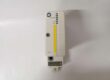
- Model: F7133
- Alt. P/N: No direct cross-replacement part; no revised hardware variant
- Product Series: HIMA HIQuad H41q / H51q Safety Instrumented System
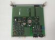
- Hardware Type: 4TE DIN rack-mounted 4-channel safety field power distribution module
- Key Feature: Individual 4A slow-blow fuses per channel + hardwired collective fault relay output
- Primary Field Use: Distribute protected 24VDC field power to F3236 DI, F6217 AI, F3330 DO I/O modules and field transmitters/solenoids for SIL3 ESD loops.
Hard-Numbers: Technical Specifications
- Protocol Support: HIMA proprietary safety backplane bus, ELOP II / SILworX diagnostic reporting
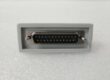
- Port Count: Front screw terminal 24VDC main input; 4 independent fused channel output terminals; rear rack edge connector for fault signal to safety CPU
- Baud/Data Rate: N/A, passive power distribution hardware with digital fault telemetry
- Operating Temperature: -20°C to +60°C operational; -40°C to +85°C storage
- Isolation Rating: 1500VAC galvanic isolation between field power circuits and safety backplane logic
- Power Draw: 24VDC rack supply, idle consumption 60mA, max 1.4W module power draw
- Channel Fuse Rating: 5×20mm slow-blow miniature fuse, max 4A per channel
- Fault Relay Spec: SPDT relay, 30VDC / 4A continuous contact load, ~100ms switching delay
- Fuse Blow Residual: 0V / 0mA residual voltage/current on tripped channel
- Loss Of Supply Residual: ≤3V residual voltage, <1mA leakage current with main input removed
- Certifications: IEC 61508 SIL3, ATEX Zone 2 compatible, CE Class B EMC, UL recognized
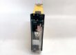
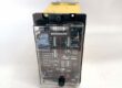
- Form Factor: 4 TE slot width, IP20 cabinet-only installation
- Weight: 0.25kg single module unit
The Real-World Problem It Solves
Running all I/O field power off a single unmonitored 24V rail creates total SIS signal loss if one channel shorts and blows a single main fuse. Generic terminal block fuse splits lack per-channel fault signaling to the safety CPU, so blown field circuits remain hidden until a safety trip event fails to execute.Where you’ll typically find it:
- Refinery HIPPS reactor racks feeding 4-20mA transmitters and ESD blowdown solenoid valves
- Offshore FPSO fire gas detector and valve position feedback DI power distribution cabinets
- Fossil power plant boiler BMS SIL3 safety racks powering furnace pressure transmitters and fuel shutoff DOsThis fused multi-channel power splitter isolates short-circuit faults to one circuit and sends fuse trip alarms to the safety CPU for operator DCS notification.
Hardware Architecture & Under-the-Hood Logic
This passive power distribution board has basic fault monitoring logic with no dedicated high-speed processor; it taps main 24VDC input and splits to four electrically separated fused output branches.
- 24VDC main field power enters front input terminal block, passes through common EMI filter to suppress mains transients.
- Four independent circuit paths route power to front output terminals, each protected by a replaceable 4A slow-blow fuse.
- Individual voltage sense circuits monitor each fuse leg; loss of channel voltage triggers a collective fault relay.
- Hardwired SPDT relay contacts close on any blown fuse, sending discrete fault signal to the rack safety backplane.
- Front panel individual LED indicators light red for each channel with blown fuse for instant cabinet visual troubleshooting.
- Isolated rear edge connector transmits fault status bits to HIMA safety CPU for logging and DCS alarm forwarding via F8621A communication modules.
Field Service Pitfalls: What Rookies Get Wrong
Overfusing Channels With Higher Than 4A Replacement Fuses
Most apprentices swap blown fuses with 5A/6A generic fuses to avoid repeat trips. Oversized fuses fail to cut short-circuit current fast enough, burning internal module PCB traces and risking unprotected field wiring fire hazards.Field Rule: Only install factory-specified 4A slow-blow 5×20mm fuses for all F7133 output channels; label spare fuse stock clearly to prevent mix-ups.
Daisy-Chaining Multiple I/O Module Field Power Off One F7133 Channel
Techs stack 3+ solenoid valves or high-current transmitters onto a single fused 4A channel. Combined load current exceeds fuse rating, causing chronic nuisance fuse trips during normal plant operation.Quick Fix: Limit maximum load per F7133 channel to 3A continuous; split high-current solenoid banks across separate module output channels.
Ignoring Fault Relay Wiring For DCS Alarm Notification
Crews skip wiring the F7133 fault relay contacts to DI input modules. Blown field fuses generate no plant operator alarm, leaving disabled safety circuits undetected for weeks until a process upset occurs.Field Rule: Hardwire the F7133 collective fault relay to a spare F3236 DI channel; map the fault bit to a high-priority DCS alarm in ELOP II safety logic.
Commercial Availability & Pricing Note
Please note: The listed price is for reference only and is not binding. Final pricing and terms are subject to negotiation based on current market conditions and availability.