

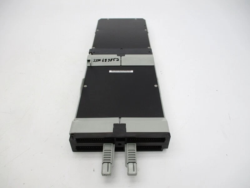
Component Snapshot At-a-Glance
- Model: CP60 (Factory part marking: P0961FR); simplex variant = CP60S
- Alt. P/N: No direct cross-brand replacement; only factory /CP60S revision suffix options
- Product Series: Foxboro I/A Series Classic DCS Platform
- Hardware Type: Backplane rack mount primary DCS control CPU/Nodebus master controller
- Key Feature: Dual-card redundant hot standby with bumpless zero-process-drop failover capability
- Primary Field Use: Executes PID/cascade/sequential interlock logic, polls all rack FBM I/O via Nodebus and routes data to operator HMI workstations
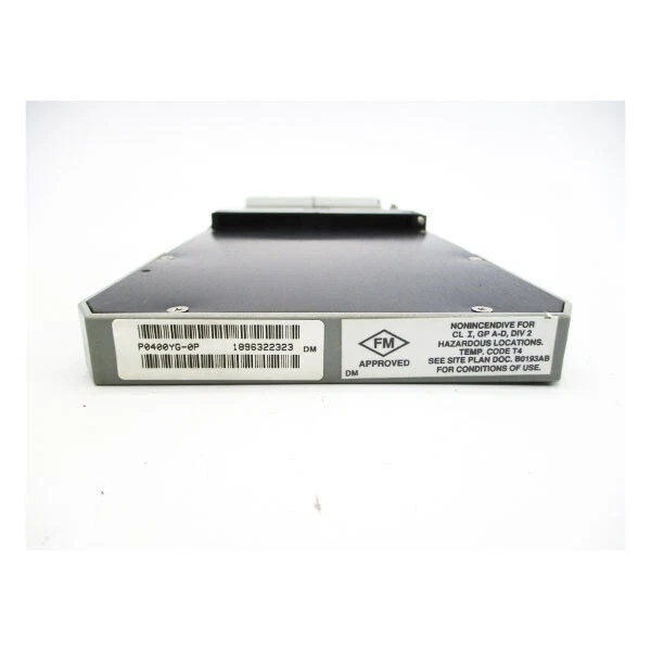
P0400YG
Hard-Numbers: Technical Specifications
- Protocol Support: 2Mbps Foxboro Nodebus, 10/100BaseTX Ethernet, RS232 HDLC, Modbus RTU/TCP
- Port Count: 1 front RJ45 LAN, 1 front RS232 debug port, rear goldfinger Nodebus backplane edge connector
- Baud/Data Rate: Nodebus fixed 2Mbps; Ethernet auto 10/100Mbps; RS232 max 19200 baud
- Operating Temperature: 0°C ~ +60°C continuous cabinet ambient; storage -40℃~+85℃
- Isolation Rating: 1500VAC galvanic isolation between field comm ports and internal CPU core power rail
- Power Draw: 8.5W nominal @ regulated 24VDC SELV rack supply
- Max Direct FBM Capacity: 32 FBM cards per local backplane; expand to 128 FBM via FEM100 expansion chassis
- Onboard Memory: 8MB program flash RAM, 4MB real-time process database RAM (32-bit RISC core)
- Hot-Swap Rating: Full live extract/insert only permitted on redundant paired rack configuration
The Real-World Problem It Solves
Older I/A CP40/CP50 controllers cap out at fewer than 22 local FBMs and lack native auto-failover, forcing full rack power down to swap failed CPU and triggering unplanned process trips at refining and utility sites. Stacking extra standalone CPU racks adds dozens of intermediate marshalling terminals that introduce loose wiring faults and periodic I/O dropout.Where you’ll typically find it:
- Coal-fired power plant boiler feedwater & furnace combustion main DCS control racks
- Petrochemical crude distillation column cabinets running cascade temperature/pressure control loops
- Onshore natural gas compressor station DCS enclosures for wellhead interlock and flow regulation
Redundancy design plus expanded local FBM count eliminates extra auxiliary control racks and cuts unplanned downtime from single CPU component failure.
Hardware Architecture & Under-the-Hood Logic
This module splits internal circuitry into isolated CPU core and Nodebus transceiver sections with independent power filtering; paired redundant CP60s sync full control database across dedicated backplane interlock bus without shared field ground paths.
- Rear backplane goldfingers pulls regulated 24VDC rack power and Nodebus polling frames from baseplate bus rail.
- 32-bit onboard RISC core loads pre-stored control logic from flash memory and runs continuous PID, sequence and safety interlock calculations.
- Calculated output setpoints get encapsulated into Nodebus data packets and transmitted to corresponding FBM I/O modules across the rack.
- Raw field measurement data from all connected FBMs passes isolation barrier before updating the ’s real-time internal database and alarm threshold triggers.
- Front panel LED array independently tracks CPU run state, Ethernet link status, Nodebus sync, redundant partner health for quick on-site fault spotting.
Field Service Pitfalls: What Rookies Get Wrong
Mismatched Firmware Build Between Redundant CP Pair
New field tech installs different firmware revisions on primary and standby ; standby card cannot mirror runtime database and fails automatic switchover during active CPU fault.
- Field Rule: Confirm identical exact firmware build numbers on both redundant units before rack power-up.
Exceed 32 Direct Local FBM Limit On Baseplate
Technician mounts over 33 FBM modules directly to host rack; Nodebus bus loading spikes past rated threshold leading to intermittent random FBM offline and FAULT LED flashing.
- Quick Fix: Shift surplus FBM hardware onto FEM100 expansion rack once local FBM count hits 30 total.
Route Unshielded LAN Next To VFD Power Cabling
Improper cable routing runs bare CAT5 Ethernet alongside variable frequency drive three-phase wiring; radiated EMI corrupts HMI-CPU Ethernet traffic causing sporadic workstation disconnects.
- Field Rule: Deploy shielded industrial CAT6 cable and separate data trays from high-current AC power wiring by minimum 15cm clearance.
Commercial Availability & Pricing Note
Please note: The listed price is for reference only and is not binding. Final pricing and terms are subject to negotiation based on current market conditions and availability.


