
Description
Hard-Numbers: Technical Specifications
- Supply Voltage: 20-40 VDC low-voltage model (nominal 24 VDC); minimum 15 W power capacity required
- Actuator Output: 0-400 mA current drive to fuel metering actuator
- Speed Demand Input: 4-20 mA or 1-5 VDC analog setpoint
- Speed Ranges (Selectable) : 500-1500 Hz, 2000-6000 Hz, 1000-3000 Hz, 4000-12000 Hz
- Rated Speed Adjustment: Up to 11,450 Hz via multi-turn potentiometer
- Generator Inputs: PT 95-130 VAC 3-phase, CT 3-7 A RMS at full load
- Operating Temperature: -40°C to +85°C (-40°F to +185°F)
- Storage Temperature: -40°C to +70°C (-40°F to +158°F)
- Dimensions: 15.25″ W × 7.125″ H × 2.5″ D (387 × 181 × 63.5 mm)
- Weight: 3.875 lb (1.76 kg)
- Compliance: UL Listed E97763, CE marked
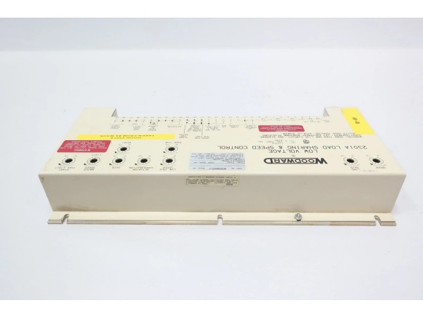
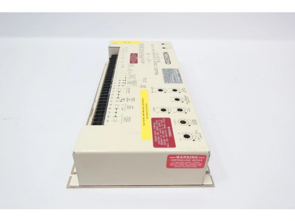
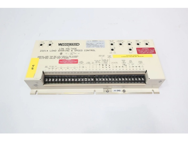
WOODWARD 9907-023
The Real-World Problem It Solves
Mechanical governors and basic speed controllers can’t handle parallel generator operation without hunting, circulating currents, and load swings. The 9907-023 provides electronic load sharing with isochronous or droop modes, eliminating manual load balancing and protecting generators from destructive load oscillations when running in parallel.
Where you’ll typically find it:
- Multi-generator power plants with diesel or gas engines requiring automatic load distribution
- Industrial cogeneration facilities where generators feed infinite buses with automatic load control
- Remote offshore rigs and mining sites with redundant generator sets needing seamless load transfer
Bottom line: This controller turns manual paralleling into automatic load sharing—generators run in sync, frequency stays within 0.01 Hz, and load changes happen without operator intervention or protective relay trips.
Hardware Architecture & Under-the-Hood Logic
The 9907-023 is a forward-acting electronic governor that converts 4-20 mA speed/load commands into 0-400 mA actuator drive. It reads speed from a magnetic pickup, calculates load from PT/CT inputs, and shares load data with other generators via analog load sharing lines. No microprocessor here—it’s analog circuitry with discrete comparators and PI control, all on a single PCB inside a metal enclosure.
- Power applied (20-40 VDC) energizes the internal supply; front-panel S1 switch selects speed range matching MPU frequency
- Magnetic pickup generates frequency signal proportional to prime mover speed; control compares to setpoint
- 4-20 mA or 1-5 VDC demand signal enters; built-in signal converter conditions input without external hardware
- PI control loop generates error correction; actuator driver outputs 0-400 mA to terminals 20/21
- PT inputs measure generator voltage; CT inputs measure current; control calculates real load (kW)
- Load sharing line outputs proportional signal to other generator controls for parallel operation
- Droop contact (terminals 14/16) selects mode—closed = isochronous, open = droop
- Actuator compensation pot tunes response (set to 2 for diesel/gas turbine, 6 for carbureted gas/steam)
- Ramp time pot limits rate of change; start fuel pot restricts fuel during cranking
- Speed trim pot (external 100 Ω on terminals 23/24) provides ±5% fine adjustment; jumper required if unused
WOODWARD 9907-023
Field Service Pitfalls: What Rookies Get Wrong
Incorrect CT Phasing
Reversed current transformer polarity makes the control calculate negative load values—load sharing fails completely. Generators either fight each other or one takes all load while the others idle.
- Field Rule: Always perform CT phasing check during commissioning using the temporary jumper procedure in the manual. Short CT secondaries before disconnecting. Verify load signal polarity by comparing actual kW meter to control reading. Wrong polarity = no load sharing + circulating currents.
Over-Turning Single-Turn Pots
Only Rated Speed is multi-turn. All others (Gain, Ramp, Droop, Compensation) are single-turn with hard 终止s. Forcing them destroys the wiper mechanism and kills the control.
- Quick Fix: Identify which pots are multi-turn before touching anything. Rated Speed turns 10 full rotations; everything else 终止s after one turn. If you hit a 终止, 终止 turning—don’t force it.
Wrong Speed Range Switch Setting
MPU frequency at rated speed must fall within the selected S1 range. 1800 RPM with 60-tooth gear = 1800 Hz. If switch is set to 500-1500 Hz, the control can’t see speed properly—output hunts or dies.
- Field Rule: Calculate frequency first: Hz = (RPM × teeth) ÷ 60. Set S1 to the range covering that value. Verify during commissioning. Wrong range = no speed control. Mark the switch position for future reference.
Missing Speed Trim Jumper
Removing the external trim pot without jumpering terminals 23 and 24 leaves the speed trim circuit open. Speed drifts erratically, or you lose fine adjustment capability.
- Quick Fix: Terminals 23/24 are either wired to a 100 Ω pot OR jumpered together. Never leave them open. If you pull the pot, install the jumper immediately.
Commercial Availability & Pricing Note
Please note: The listed price is for reference only and is not binding. Final pricing and terms are subject to negotiation based on current market conditions and availability.


