
Description
Key Technical Specifications
-
Model Number: 9905-096
-
Manufacturer: Woodward Inc.
-
Product Family: AGLC (Automatic Generator Loading Control)
-
Input Voltage: 170-264 VAC, 50/60 Hz
-
Power Consumption: 5 VA
-
Control Function: Soft loading and unloading with electronic ramps
-
Ramp Time Adjustment: 5 seconds to 5 minutes for 100% load change
-
Load/Unload Ramp Rates: Independently adjustable
-
Maximum Units Controlled: Up to 15 paralleled load-sharing generators
-
Operating Temperature: -40°C to +85°C (-40°F to +185°F)
-
Storage Temperature: -55°C to +105°C (-67°F to +221°F)
-
Shock Resistance: 60 Gs
-
Dimensions: 8.5″ W × 7.5″ H × 2″ D (216 × 191 × 51 mm)
-
Weight: 2.25 lbs (1.02 kg)
-
Certifications: UL and cUL Listed, CSA Certified
-
Chassis Construction: Metal enclosure with front-access potentiometers
-
Relay Output: Double-throw relay for unload trip contact initiation
- Base Load Setting: Internal potentiometer or external potentiometer input

WOODWARD 9905-001-G
Field Application & Problem Solved
In the field, the biggest challenge with paralleling generators isn’t getting them synchronized—that’s what your SPM-A or DSLC handles. The real problem is the “thump” when you close the breaker and immediately slam 500 kW onto a unit, or worse, the voltage dip and frequency sag when you open the breaker and dump load back onto the bus. Mechanical shock to the engine, thermal stress on the windings, and potential breaker damage from inrush currents are the consequences. The 9905-096 solves this by providing true soft loading and unloading through controlled electronic ramps that gradually transfer power over seconds or minutes rather than milliseconds.
You will typically find this module in cogeneration plants, peak-shaving facilities, and emergency backup systems where generators need to come online smoothly or transfer load without disturbing critical processes. It’s particularly common in hospital backup systems, data center power plants, and industrial facilities running multiple Caterpillar or Waukesha gensets in parallel. The 9905-096 works in conjunction with Woodward 2301A load sharing controls or other governor systems that have load sensing capability—it’s not a governor itself, but a load management interface that sits between your sync check relay and your speed control.
Its core value is eliminating the “bump” during paralleling operations. When the generator breaker closes, the AGLC doesn’t just dump the unit onto the bus—it tracks the existing load on the set and ramps the load up at a preset rate until the generator matches system frequency and voltage. For utility paralleling, it can base load a unit against the grid, holding a fixed kW output while the utility absorbs frequency variations. The unload function is equally critical—when you need to take a unit offline, the AGLC ramps the load down to an adjustable trip point (say, 50 kW) before opening the breaker, preventing the remaining online units from suddenly picking up the shed load and sagging frequency. This is essential for maintaining power quality to sensitive loads during unit transitions.
Installation & Maintenance Pitfalls (Expert Tips)
Ramp Rate Setting is Application-Specific, Not Universal
A common rookie mistake is leaving the factory default ramp rates or setting them too fast for the engine’s capability. A large diesel can accept load at 20% per second; a gas turbine might need 5% per minute to avoid flameout. If you set the ramp too aggressive, the engine lugs, exhaust temperature spikes, and you get a “failed to load” alarm. Set it too slow and you’re burning fuel at no load while waiting to parallel. Always coordinate ramp settings with the engine manufacturer’s load acceptance curve. For base load applications against the utility, slower ramps (2-3 minutes) are usually better to avoid hunting against the infinite bus.
The Unload Trip Level Must Match Your Minimum Load
The unload trip potentiometer sets the load level where the AGLC stops ramping and opens the trip relay. If you set this too low—say, 10 kW on a 1000 kW unit—you risk the engine running at no load with the breaker still closed, which can cause reverse power or motoring. If you set it too high, you never actually reach the trip point and the breaker won’t open. A good rule of thumb is 5-10% of rated load, but never less than the engine’s minimum stable load. I’ve seen installations where the trip was set to 0 kW theoretically, but in practice, the unit never unloaded completely and had to be manually tripped.
Base Load vs. Load Share Mode Wiring
The 9905-096 can operate in two distinct modes: base load (against utility) or load share (isolated bus). The mode is determined by wiring the base-load reference switch. If you’re paralleling with the utility, you close the base-load switch and set the desired kW with the potentiometer. If you’re on an isolated bus with other Woodward load sharing controls, you leave base-load open and the AGLC tracks the load sharing lines. Wiring this wrong results in the unit fighting the utility (trying to hold frequency on an infinite bus) or failing to share properly on an isolated system. Verify your breaker auxiliary contact logic before commissioning.
Load Sensing Compatibility is Critical
The AGLC requires a load sensor input—either from a 2301A with built-in load sensing or an external Woodward load sensor (like the 8290-048). If you’re retrofitting this onto an older system without load sensing, the AGLC has no feedback and won’t function. The load signal is typically 0-6 Vdc representing 0-100% load. Verify that your governor or external sensor can provide this signal and that the polarity is correct. Reversed load signal wiring causes the AGLC to think it’s at full load when it’s actually at no load, resulting in immediate trip or failed loading.
Power Supply Transients During Transfer
The 9905-096 runs on 170-264V AC, usually tapped from the generator output or station service. During paralleling operations, voltage transients or momentary dips can reset the AGLC, causing the ramp to restart mid-sequence. Ensure your power supply is stable and consider a UPS or isolation transformer if you’re seeing erratic behavior during breaker operations. The 5 VA consumption is low, but the control is sensitive to voltage sags below 170V.
Technical Deep Dive & Overview
The Woodward 9905-096 is an analog automatic generator loading control from the AGLC series, designed to manage the mechanical and electrical stress of paralleling operations in multi-generator power systems. It is not a synchronizer and it is not a governor—it is a load management interface that works downstream of synchronization to ensure bumpless power transfer.
The module receives AC power (170-264V, 50/60 Hz) and interfaces with the generator’s load sensor (either internal to a 2301A control or via external load sensor). It continuously tracks the real power output of the generator through a 0-6 Vdc analog signal. Upon receiving a breaker-close auxiliary contact input, the AGLC initiates a controlled ramp that increases the generator load from its current level (typically zero or spinning reserve) up to the system load level at a rate set by the front-panel “Load Rate” potentiometer. This ramp is achieved by biasing the speed reference of the governor—essentially telling the governor to “hold the speed but accept load” in a controlled manner.
The electronic ramp generator uses analog integrator circuits to create linear load ramps adjustable from 5 seconds to 5 minutes for full load transfer. Separate potentiometers control load and unload rates, allowing asymmetric operation—fast loading for emergency situations, slow unloading for controlled shutdowns. The ramp circuits are voltage-controlled, meaning the actual time to transfer depends on the generator’s load acceptance capability and the governor response, not just the AGLC setting.
For unloading, a momentary contact input initiates the reverse ramp. The AGLC reduces generator load at the set unload rate until reaching the adjustable “Unload Trip” level, at which point a double-throw relay de-energizes to signal the breaker opening. This prevents the sudden load dump that would otherwise cause frequency sag on the remaining online units.
In base load mode (utility paralleling), the AGLC maintains a fixed kW output set by the “Base Load” potentiometer, ignoring the load sharing lines and responding only to the internal reference. This effectively converts the isochronous governor into a droop governor with a fixed setpoint, allowing the utility to absorb frequency variations while the generator provides constant power.
The 9905-096 is specifically designed for systems requiring power to maintain the unload trip relay when contacts open (circuits that require power for disconnect), distinguishing it from the 9905-063 variant which disconnects when holding contacts open
. This “power for disconnect” logic is important for fail-safe operation in critical applications where you want the unit to unload and trip offline on loss of control power.
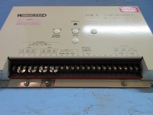
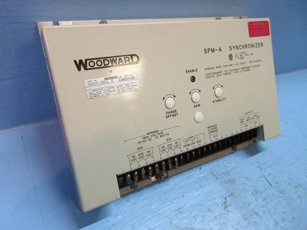
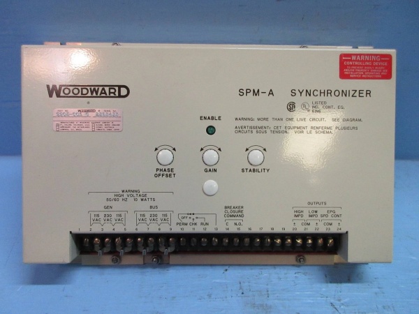
From a system architecture perspective, the 9905-096 sits between the synchronizer (SPM-A or DSLC) and the governor (2301A or equivalent). The synchronizer handles voltage, frequency, and phase matching; the AGLC handles the mechanical loading; and the governor handles speed regulation. This three-layer approach—sync, load, speed—provides precise control over the paralleling process while protecting the prime mover from thermal and mechanical shock.


