
Description
Hard Numbers: Technical Specifications
(Note: The following specifications are compiled from typical UG-8 / 8520-312 operational parameters. Please consult the official Woodward documentation for exact project engineering.)
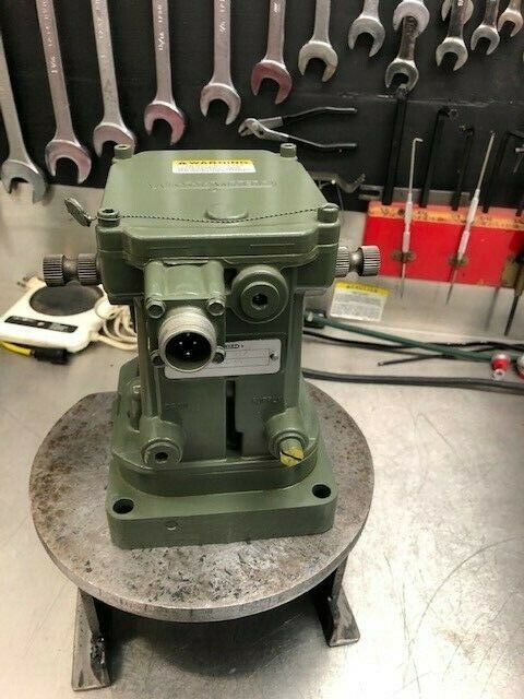
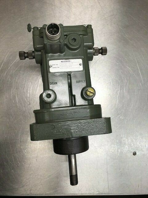
- Part Number: 8520-312
- Series: UG-8 (Standard version)
- Actuator Type: Hydraulic
- Speed Control Range: Customizable based on drive gear ratio (typically supports 600–3000+ RPM)
- Output Shaft Travel: Up to 42 degrees (depending on specific model configuration)
- Maximum Output Torque: Up to 34 N·m (300 lb-in)
- Hydraulic Operating Pressure: 415–620 kPa (60–90 psi) inlet pressure; 1400–1725 kPa (200–250 psi) outlet pressure
- Lube Oil Requirement: Clean, light lubricating oil (e.g., SAE 10W or equivalent)
- Ambient Temperature Range: -40°C to +93°C (-40°F to +200°F)
- Mounting Orientation: Typically foot-mounted, designed for direct linkage to the engine’s fuel rack or steam valve
- Manual Overspeed Trip: Equipped with a standard overspeed trip mechanism (can be reset manually or electronically depending on variant)
The Real-World Problem It Solves
Picture a massive 2-stroke marine diesel engine pushing a cargo ship through a stormy Atlantic. The engine is vibrating, temperatures are extreme, and salt spray is everywhere. In this environment, electronic circuit boards (like the 8270 series) can fail due to corrosion or electrical spikes.
Enter the Woodward 8520-312 (UG-8). This is a beast of pure mechanical and hydraulic ingenuity. It doesn’t need a single volt of electricity to regulate the engine’s speed. It uses a rotating flyweight mechanism driven directly off the engine’s camshaft. As the engine speed changes, centrifugal force moves the flyweights, which shifts a precision pilot valve. This valve directs pressurized oil to move a powerful piston, which in turn pushes or pulls the engine’s fuel rack .
Because it relies on the fundamental laws of physics rather than microprocessors, the UG-8 is virtually immune to electromagnetic interference (EMI), voltage drops, or sensor failures. It provides a massive amount of mechanical advantage, meaning it can muscle through dirty, sticky, or heavy fuel racks that would stall an electric actuator. For legacy engines and mission-critical applications where “it just has to run,” the 8520-312 remains the undisputed king of reliability .
Where you’ll typically find it:
- Marine Main Propulsion: Controlling the massive fuel racks on large-bore diesel engines where brute force and zero electrical dependency are required .
- Old-School Power Stations: Governing the speed of steam turbines or large generator sets in harsh, electromagnetically noisy environments .
- Oil Field Pumpjacks: Providing reliable, 24/7 speed regulation for natural gas engines driving pumps in remote, unmanned locations .
Hardware Architecture & Under-the-Hood Logic
Unlike modern electronic governors that rely on PID algorithms and microchips, the UG-8 operates on elegant, robust fluid dynamics and centrifugal force.
- The Sensing Element (Flyweights): A drive shaft connected to the engine’s camshaft spins a set of precisely weighted flyweights. As engine speed increases, centrifugal force causes the flyweights to fly outward, lifting a thrust bearing and a linked pilot valve stem .
- The Pilot Valve (The Brain): The pilot valve is an extremely tight-fitting spool valve. A microscopic movement (thousandths of an inch) of the pilot valve caused by the flyweights is enough to redirect the flow of pressurized oil. This is the “amplification” stage—turning a tiny mechanical motion into a powerful hydraulic action .
- The Power Piston (The Muscle): The redirected oil flows into a large diameter power cylinder. Because fluid pressure is acting on a large surface area, it generates immense force. This piston is mechanically linked to the engine’s fuel control lever (or steam admission valve). As the piston moves, it adjusts the fuel flow to bring the engine speed back to the setpoint .
- The Buffer Valve (The Damper): Directly connected to the power piston is a buffer valve. As the piston moves rapidly, the buffer valve restricts the flow of oil, creating a damping effect. This prevents the governor from overcorrecting and stops the engine speed from oscillating (hunting) .
Field Service Pitfalls: What Rookies Get Wrong
The “Milky” Oil Disaster (Water Contamination)
The UG-8 relies on a constant supply of clean, dry lubricating oil (usually supplied by the engine’s own lube oil system) to operate its internal pilot valve and power piston.
- The Symptom: The governor becomes sluggish, responds slowly to load changes, or the engine starts “hunting” (cyclical speeding up and slowing down). Eventually, the internal components can rust and seize solid.
- The Cause: Water has entered the lube oil system (common in marine environments or due to condensation). When water mixes with hot oil, it creates a milky emulsion that has the viscosity of mayonnaise. This sludge cannot properly lubricate the tight tolerances of the pilot valve.
- Field Rule: Never ignore milky-looking oil samples. Install or check the governor’s water traps and drains daily. If water ingress is a chronic issue, consider installing a dedicated kidney-loop filtration system with a coalescing filter to remove water before the oil reaches the governor .
Linkage Geometry Errors (The “Cosine” Loss)
The UG-8 actuates the engine’s fuel rack via a mechanical linkage (rods, bell cranks, and clevis pins). Rookies often disconnect the linkage to perform maintenance and reattach it incorrectly.
- The Glitch: If the linkage is not perfectly aligned at the midpoint of the governor’s travel, the relationship between the governor’s output and the fuel rack position becomes non-linear (a geometric cosine error). The engine might respond perfectly at half throttle but become dangerously unresponsive at full load, or vice versa.
- Field Rule: Always use a protractor or angle gauge when reconnecting the linkage. Ensure the governor’s output lever and the engine’s fuel rack lever are exactly parallel to each other at the mid-stroke position. Use the same number of turns when tightening clevis pins to ensure equal thread engagement .
Ignoring the “Dead Band” Adjustment
Every UG-8 governor has a small amount of deliberate “dead band” (a slight delay in response) to prevent it from constantly chasing minute fluctuations in engine speed. Over time, as internal springs weaken and pivot points wear, this dead band can widen.
- The Consequence: The engine operator notices that the RPM is drifting significantly (e.g., 5-10%) before the governor decides to make a correction. This is especially dangerous in generator sets paralleled with other units (isochronous load sharing), as it can cause massive reactive power swings and potentially trip the generator offline.
- Field Rule: Periodically test the governor’s dead band. Using a precise digital tachometer, slowly increase and decrease the load while monitoring the speed. If the speed change exceeds 1-2% before the governor reacts, the internal compensating springs or buffer valve settings need to be adjusted or the unit needs an overhaul .
Commercial Availability & Pricing Note
Please note: The listed price is for reference only and is not binding. Final pricing and terms are subject to negotiation based on current market conditions and availability.


