
Description
Key Technical Specifications
Model Number: 8406-121
Manufacturer: Woodward Inc.
Product Family: EGCP-2 Engine Generator Control Package
Power Supply: 9-32 Vdc (SELV), 12V or 24V nominal
Power Consumption: ≤13 W nominal, 20 W maximum
PT Input Voltage: 50-150 Vac (distinguishes 8406-121 from 8406-120 which is 150-300 Vac)
CT Input: 0-5 A rms
Generator Frequency Range: 40-70 Hz
Magnetic Pickup Input: 100-1000 Hz
Discrete Inputs: 16 channels, 0 mA source current when closed to switch common
Discrete Outputs: Relay outputs rated 10A at 250 Vac resistive, 10A at 30 Vdc resistive
Analog Outputs: Multiple options including 4-20 mA, 0-10 Vdc, ±3 Vdc, ±9 Vdc, PWM
Process Inputs: 4-20 mA, 1-5 Vdc transducers
Temperature/Pressure Inputs: 0-200 Ω sensors, 4-20 mA, or 0-5V
Communication: Modbus RTU/ASCII via RS-422/RS-485; EGCP-to-EGCP network via RS-485
Display: Two backlit LCDs with 8 lines × 20 characters each, plus membrane keypad
Operating Temperature: -20°C to +70°C (-4°F to +158°F)
Storage Temperature: -40°C to +105°C (-40°F to +221°F)
Relative Humidity: 95% non-condensing at 30-60°C
Vibration: SV2 5-2000 Hz @ 4G; RV1 10-2000 Hz @ 0.04 G²/Hz
Shock: US MIL-STD-810C, Method 516.2
Ingress Protection: IP56 (when installed in suitable vented enclosure), Type 4
Dimensions: 282 mm (11.1″) H × 358 mm (14.1″) W × 69 mm (2.7″) D
Weight: ~0.9-2.0 kg (varies by source)
Regulatory Compliance: UL/cUL listed, CSA certified, EMC and Low Voltage Directives
Maximum Unit Power: Up to 30 MW per generator
Network Capacity: Up to 8 generator sets in automatic sequencing
WOODWARD 9905-001-G
Field Application & Problem Solved
In the field, the biggest challenge with generator set control is integration. You used to need separate boxes for engine governing, generator voltage regulation, synchronizing, load sharing, and protection—each with its own wiring, configuration, and failure modes. Getting them to talk to each other was a nightmare of inter-wiring and timing conflicts. The 8406-121 solves this by putting everything in one microprocessor-based package: engine control, generator excitation, automatic synchronization, real and reactive load sharing, sequencing, and full protection—all integrated with a common operator interface and communication network.
You will typically find this controller in standby power systems for hospitals, data centers, and critical infrastructure; prime power applications for remote sites, mining operations, and marine vessels; and peak-shaving or cogeneration plants where multiple generators need to start, synchronize, and share load automatically based on system demand. It’s designed for diesel or gas engines driving synchronous generators up to 30 MW, handling everything from pre-lube and fuel control to breaker closing and utility paralleling.
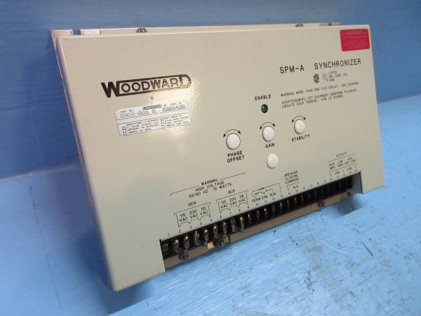
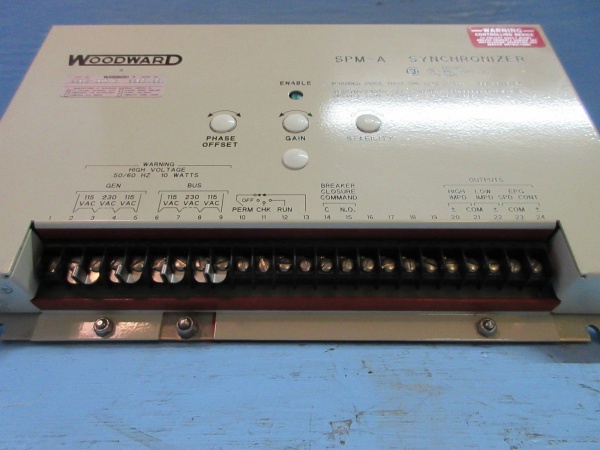
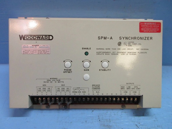
Its core value is reducing installation complexity and improving reliability by eliminating external control modules. The automatic generator sequencing feature lets you start and stop units based on actual load demand, equalizing runtime across your fleet. The integrated synchronizer checks voltage, frequency, and phase angle before closing the breaker—no separate SPM-A or DSLC required. The load sharing manages both kW (via speed bias) and kVAR (via voltage bias) through the RS-485 EGCP-to-EGCP network , keeping all units in proportion without external load sensors. Protection functions include over/under voltage and frequency, reverse power and VARs, overcurrent with inverse time delay, loss of utility, and full engine protection (overspeed, high/low oil pressure, coolant temperature) . The Modbus communication lets you monitor and control from a SCADA system or PC running EGCP-2 Control View software.
Installation & Maintenance Pitfalls (Expert Tips)
PT Input Range Determines Model Selection
The 8406-121 is specifically the 50-150 Vac PT input variant . The 8406-120 is 150-300 Vac. A common field mistake is ordering the wrong part number for your generator voltage. If you have a 480V generator with 120V PT secondaries, the 8406-121 works fine. But if you have a 4160V generator with 240V PT secondaries, you need the 8406-120. Applying 240V to the 8406-121’s PT inputs will destroy the voltage sensing circuits. Always verify your PT secondary voltage before ordering and installing.
EGCP-to-EGCP Network Wiring is Not Standard RS-485
While the EGCP-2 uses RS-485 for its inter-unit communication , the network topology has specific requirements. The “stub length” from the main trunk to each unit must be minimized—preferably under 600 mm . I’ve seen installations where technicians ran long drops to each genset, creating signal reflections that caused intermittent communication failures. The network would work fine with two units, then fail when a third came online. Use a proper trunk-and-drop topology with termination resistors at both ends of the main bus, and keep your drops short.
Auto-Sequencing Logic Requires Proper Load Calculation
The automatic start/stop sequencing is powerful but dangerous if misconfigured. The system starts units based on “system load demand” setpoints, but these must be calculated based on your actual load profile, not nameplate ratings. Setting the start threshold too low causes excessive cycling; too high and you overload running units before starting the next. Worse, the “off-line engine priority” feature can start the wrong unit if priorities aren’t assigned logically. During commissioning, run a full load test across all possible combinations and verify the sequencing logic under real conditions.
Synchronizer Settings Must Match Breaker Dynamics
The integrated synchronizer is convenient but not foolproof. The “breaker close anticipation” timing must match your actual breaker closing time—typically 3-8 cycles for medium-voltage air circuit breakers. If you set the anticipation too short, the breaker closes after the sync point; too long, and you close before synchronization. This causes mechanical stress and potential damage. Measure your actual breaker closing time with a high-speed timer during commissioning, then set the anticipation accordingly. Also verify the phase rotation—reverse generator rotation will prevent synchronization entirely.
Modbus Register Mapping is Not Standard
The Modbus implementation uses Woodward-specific register mappings. Don’t assume standard addressing—consult manual 26181 for the complete communication protocol. I’ve seen SCADA integrators waste days trying to read power values from the wrong registers. The EGCP-2 Control View software is essential for initial setup and troubleshooting; keep a laptop with this software available for field service. Note that the RS-422/RS-485 port is used for both Modbus and the EGCP-to-EGCP network—don’t try to use them simultaneously without proper network configuration.
Engine Protection Setpoints Must Be Coordinated
The 8406-121 includes comprehensive engine protection , but these setpoints must coordinate with your engine manufacturer’s limits. A common mistake is setting the overspeed trip at 110% when the engine’s mechanical overspeed is set at 115%—you want the electronic protection to act first. Similarly, oil pressure and coolant temperature alarms must be set with appropriate time delays to prevent nuisance trips during startup. The “start failure” timer must account for your specific engine’s cranking characteristics; diesel engines in cold climates need longer crank times than gas engines in warm environments.
The Display Backlight Has Auto-Dimming Logic
The two backlit LCDs stay lit when engine speed is above 50 RPM, but dim after 5 minutes of inactivity when the engine is stopped . This saves power but confuses operators who think the unit is powered down. The backlight also dims when supply voltage drops to conserve power . If your operators report “blank screens,” check the engine status and battery voltage before assuming display failure.
Technical Deep Dive & Overview
The Woodward 8406-121 is a microprocessor-based integrated generator and engine control system from the EGCP-2 series, designed as a complete automation solution for diesel and gas engine generator sets . Unlike the 2301A (which is purely a speed/load governor) or the 505 (which is for steam turbines), the EGCP-2 is a comprehensive package that replaces multiple discrete controllers with a single integrated platform.
The control architecture centers on a microcontroller that manages multiple control loops simultaneously: engine speed governing (via analog or PWM outputs to fuel actuators), generator voltage regulation (via analog outputs to AVR), automatic synchronization (phase/frequency/voltage matching), and real/reactive load sharing (via RS-485 network to other EGCP-2 units) . The system uses 16 discrete inputs for status monitoring (breaker position, engine alarms, mode selection) and relay outputs for control (fuel solenoid, starter motor, breaker close coil) .
The 50-150 Vac PT input range distinguishes the 8406-121 from the 8406-120 (150-300 Vac). This voltage feeds internal isolation transformers and analog-to-digital converters for voltage, frequency, and phase angle calculations. Current transformers (0-5 A) provide generator current for power calculation and overcurrent protection . Magnetic pickup inputs (100-1000 Hz) provide engine speed feedback .
The EGCP-to-EGCP network uses RS-485 differential signaling for robust communication between units. This network carries load sharing information (kW and kVAR), sequencing commands, and system status. The Modbus RTU/ASCII interface on the same physical layer (or separate port depending on configuration) allows external SCADA systems to monitor and control the plant. The EGCP-2 Control View HMI software provides PC-based monitoring, parameter editing, and trending.
From a system architecture perspective, the 8406-121 can operate in multiple configurations: single unit standby or prime power; single unit paralleled with utility (baseload, process, or soft transfer modes); multiple units in island mode with load sharing; or multiple units paralleled with utility . The automatic sequencing feature manages start/stop decisions based on system load demand, with configurable priority schemes to equalize runtime across units.
The protection systems are comprehensive: generator electrical protection (over/under voltage/frequency, reverse power/VARs, overcurrent, loss of utility) and engine mechanical protection (overspeed, oil pressure, coolant temperature, battery voltage, start failure) . These are coordinated through the microcontroller with appropriate time delays and alarm/trip hierarchies.
The 9-32 Vdc power input with SELV (Safety Extra-Low Voltage) rating makes this suitable for battery-powered applications, with internal DC-DC conversion generating isolated voltages for analog circuits and relay coils. The IP56/Type 4 environmental rating (when properly enclosed) allows installation in harsh industrial environments. The MIL-STD shock and vibration ratings ensure survival on engine skids and in seismic zones.


