
Description
Hard-Numbers: Technical Specifications
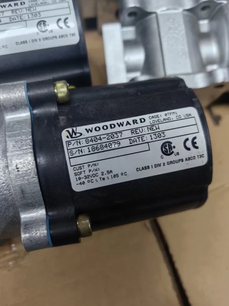
- Part Number: 8404-2037
- Control Signal: 4–20 mA DC (4mA = Min Fuel, 20mA = Max Fuel)
- Output Torque: 25 ft-lb (34 J) standard (31 ft-lb optional)
- Rotational Travel: 42° maximum (adjustable mechanical stops)
- Position Feedback: Internal magnetic resolver (Closed-loop accuracy ±0.5%)
- Hydraulic System: Self-contained sump (2.1 L / 2.2 qt), 150 psi (1034 kPa) relief pressure
- Power Supply: 24 VDC (±10%), 2.5 A max
- Operating Temperature: 0°C to +55°C (32°F to 131°F)
- Vibration Rating: 10 g (IEC 60068-2-6, engine-mounted)
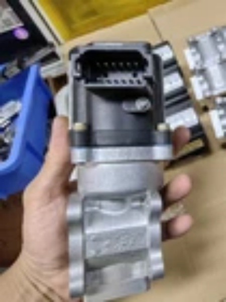
- Protection Class: IP45 (unit), IP56 (front panel with proper conduits)
WOODWARD 8404-2037
The Real-World Problem It Solves
Electronic governors (like the 2301A or 723+) are great at calculating throttle positions, but they lack the physical muscle to push a diesel fuel rack against spring tension. The 8404-2037 bridges this gap by taking the low-energy 4-20mA command and using an internal hydraulic system to amplify it into 25 ft-lb of rotational torque. It eliminates the deadband and hysteresis common in purely electric actuators, ensuring the throttle moves exactly when and how much the governor demands.
Where you’ll typically find it:
- Bolted directly onto the side of a CAT, Waukesha, or Yanmar diesel genset, replacing a failed UG-8 or 3161 governor.
- Controlling the throttle shaft of a natural gas compressor engine in a pipeline station.
- Mounted on the fuel injection pump of a marine propulsion engine, battling constant vibration and salt spray.
It turns a fragile electronic signal into brute mechanical force.
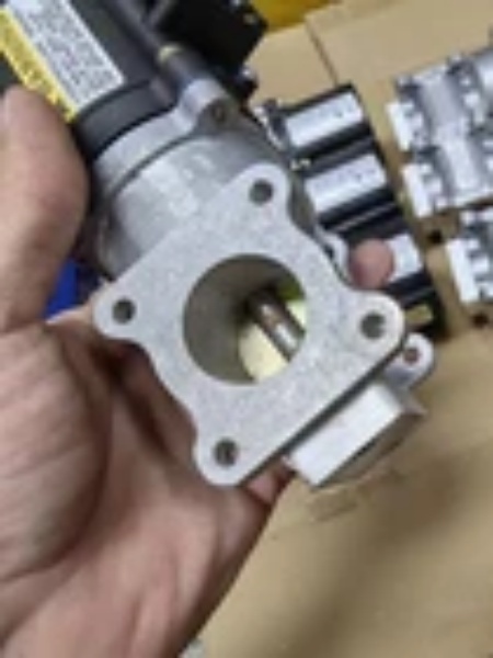
Hardware Architecture & Under-the-Hood Logic
Unlike a simple electric motor, the UG25+ uses a closed-loop electro-hydraulic system. It is essentially a self-contained hydraulic power unit with a digital brain, sitting right on the engine.
- Signal Conversion: The internal driver board receives the 4-20mA command from the upstream governor and converts it into a proportional current drive for the main solenoid valve.
- Hydraulic Amplification: The solenoid modulates internal hydraulic pressure (generated by an integral pump and stored in the 2.1L sump). This pressure acts on a hydraulic piston, translating linear force into the 42° rotary output shaft motion.
- Closed-Loop Positioning: An internal magnetic resolver continuously measures the exact position of the output shaft. This feedback is compared to the incoming 4-20mA command.
- Error Correction: If there is any deviation (due to fuel rack binding or load changes), the digital driver instantly adjusts the hydraulic pressure to eliminate the error, maintaining shaft accuracy within ±0.5%.
WOODWARD 8404-2037
Field Service Pitfalls: What Rookies Get Wrong
Running the Actuator Without Proper Oil Level
Junior techs often treat this unit like a solid-state black box, ignoring the hydraulic sump. Over time, internal seals weep, or oil gets pushed out the breather during thermal expansion. Low oil leads to cavitation, erratic shaft movement (“jitter”), and eventual burnout of the hydraulic pump.
- Field Rule: During monthly PMs, pop the filler cap and check the dipstick. The oil should be up to the “FULL” mark. If it’s low, top it off with clean ISO VG 46 hydraulic oil. If the oil is milky (water contamination) or smells burnt, drain and refill immediately.
Mismatched 4-20mA Scaling Causing Non-Linear Response
A common mistake during commissioning is assuming 4mA equals 0% and 20mA equals 100%. Depending on the linkage ratio and the upstream governor’s configuration, the effective range might be 8mA to 16mA. If the rookie doesn’t calibrate the min/max stops to the actual signal range, the actuator will “clip” at the ends, causing poor speed regulation under load.
- Field Rule: Perform a full stroke test. Command 4mA and 20mA from the governor, and physically measure the output shaft rotation. Adjust the internal mechanical stops so the shaft hits its limits exactlyat the governor’s min and max signals. Never force the shaft against the stops by over-driving the signal.
Ignoring the “Unit Healthy” LED Status Codes
When the red “Unit Healthy” LED goes out or starts flashing, rookies often just cycle the 24VDC power, hoping it resets. The LED is actually a diagnostic tool. A flashing light indicates specific faults like overcurrent (binding linkage) or overtemperature.
- Field Rule: If the light goes out, check the 24VDC supply voltage first (look for voltage drop under load). If it’s flashing, disconnect the linkage and command the actuator to move. If it still flashes, the internal solenoid or driver board is toast. If it stops flashing, your mechanical linkage is too tight or corroded—free it up before reinstalling.
Commercial Availability & Pricing Note
Please note: The listed price is for reference only and is not binding. Final pricing and terms are subject to negotiation based on current market conditions and availability.


