
Description
Hard-Numbers: Technical Specifications
- Part Number: 8200-1302
- Power Supply: 18 – 36 VDC (Isolated, typical 24VDC industrial standard)
- Power Consumption: < 25 Watts (Max ~4.3A inrush/draw)
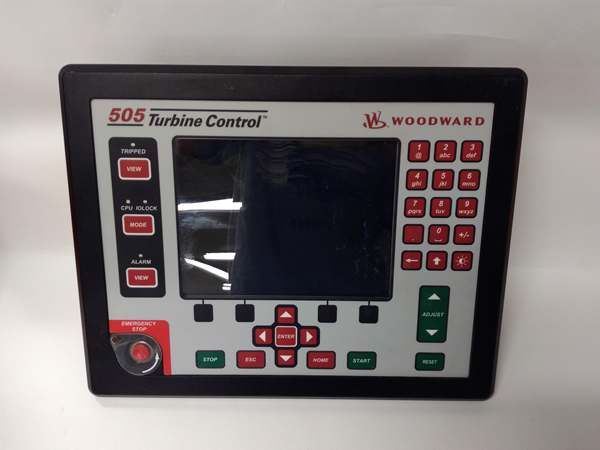
- Display & Interface: 8.4-inch color LCD with graphical HMI and tactile keypad
- Control Modes: Speed control, Load control, Pressure control, Ratio/Limiter
- Inputs: 8 Analog inputs (4-20mA, configurable), 20 Discrete inputs (including 4 default: Stop, Reset, Raise, Lower), 2 Redundant Speed sensing inputs (MPU/Eddy Current)
- Outputs: 2 Analog outputs (4-20mA), 8 Form-C Relay outputs
- Communication: Modbus RTU/ASCII, Ethernet, CANopen
- Operating Temperature: -30°C to +70°C (-22°F to 158°F)
- Enclosure Rating: IP54 (Optional marine-grade available)
- Certifications: ATEX Zone 2, IACS UR E10 (Marine), CE/UL/CSA
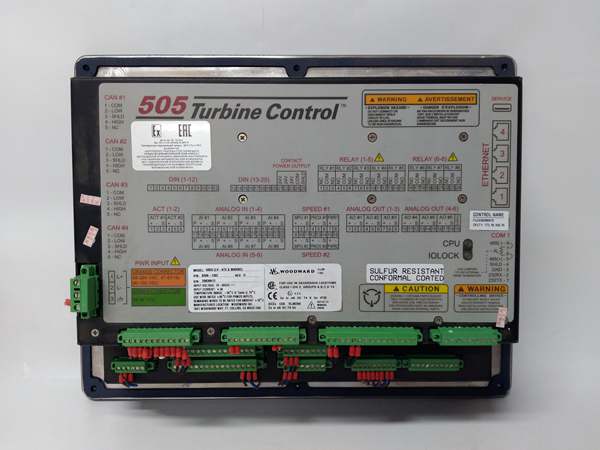
8200-1302
The Real-World Problem It Solves
Legacy mechanical-hydraulic governors and first-generation digital controllers often lack the computational power to handle complex turbine dynamics, leading to inefficient fuel consumption, harmful emissions, and risky manual synchronizations. The 8200-1302 acts as a direct, drop-in modernization solution. It replaces outdated analog logic and clunky external HMI panels with a single, unified microprocessor unit. Its dual-redundant speed inputs and advanced control algorithms allow it to smoothly pilot heavy industrial rotors through acceleration, bypassing damaging resonant frequencies (critical speeds) entirely automatically.
Where you’ll typically find it:
- Bolted to the local control panel of a multi-megawatt steam turbine in a CHP plant, managing inlet valves and extraction pressures while displaying real-time trend graphs on its 8.4″ screen.
- Serving as the primary overspeed and load governor for gas compressor drives in remote pipeline stations, communicating seamlessly with the plant’s main DCS via Modbus.
- Retrofitted into aging marine propulsion systems to replace obsolete 505-series units, providing modern Ethernet diagnostics and reducing overall panel footprint.
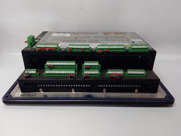
Hardware Architecture & Under-the-Hood Logic
The 8200-1302 is a purpose-built, high-speed industrial controller running deterministic real-time code tailored specifically for the thermal and rotational physics of prime movers.
- Redundant Signal Acquisition: The module continuously polls its two independent speed inputs (typically from Magnetic Pickups or Eddy Current probes). It cross-checks these signals against each other to detect sensor failure. If one sensor fails or reads erratically, it seamlessly flips to the redundant channel without tripping the turbine.
- OptiTune Adaptive PID Processing: Static PID loops are useless on turbines, which change behavior as they heat up and slow down. The 8200-1302 uses adaptive gain scheduling. During cold startup, it applies softer gains to prevent valve “hunting.” Once the rotor is spinning and carrying load, it dynamically shifts to aggressive gains to tightly lock onto grid frequency.
- Critical Speed Windowing: The firmware maintains an internal map of the turbine’s known critical speeds (resonant frequencies). As the turbine accelerates, the controller intentionally slews the RPM through these dangerous zones as quickly as possible, then automatically eases the acceleration rate once past the resonance.
- Actuator Command & HMI Rendering: Based on the calculated error, the processor generates precise 4-20mA command signals for the fuel or steam control valves. Simultaneously, the onboard graphics co-processor updates the local 8.4″ LCD, rendering valve positions, alarm banners, and trend curves with zero perceived lag.
8200-1302
Field Service Pitfalls: What Rookies Get Wrong
Botching the “Raise/Lower” Inversion During First Fire
When commissioning a newly installed 8200-1302, greenhorns often load the generic configuration file, flip the turbine to “Auto,” and hit the Raise Speed button, only to watch in horror as the RPM drops. They accidentally mapped the Raise/Lower discrete inputs backward in the software, causing the valve to close when it should open.
- Field Rule: Before connecting the output current to the real valve, hook up a temporary analog meter (or watch the software’s trend graph). Manually toggle the Raise and Lower buttons on the HMI. If the output current goes down when you press Raise, invert the logic in the I/O configuration menu immediately.
Ignoring the Isolated Power Supply Requirements
Rookies often try to power the 8200-1302 straight from a shared, noisy 24VDC bus bar alongside variable frequency drives (VFDs) and contactor coils. The resulting voltage dips and inductive spikes during motor starting cause the 505D to reboot mid-cycle, initiating an emergency turbine trip.
- Field Rule: The 18-36VDC supply input is isolatedfor a reason. Always feed this unit from a dedicated, regulated DC power supply (preferably with battery backup). Install a 5A fast-blow fuse on the positive leg, and keep the supply wires as short and thick as possible to prevent voltage drop during the initial LCD boot-up surge.
Forgetting to Bypass Critical Speed Trips During Initial Config
A classic rookie mistake is leaving all the default protection alarms armed while trying to perform the initial spin-up test. The turbine will accelerate smoothly until it hits the first critical speed band (e.g., 1500 RPM), where normal vibration limits are exceeded. The unit instantly registers a vibration fault and slams the turbine to a halt.
- Field Rule: During initial commissioning and mechanical checkout, go into the Configuration Modeand temporarily disable the vibration and critical speed trip multipliers. You want the turbine to sail through the resonances so you can gather actual vibration data. Once you know the real mechanical limits, re-enable the protections and lock the configuration.
Commercial Availability & Pricing Note
Please note: The listed price is for reference only and is not binding. Final pricing and terms are subject to negotiation based on current market conditions and availability.


