
Description
Hard-Numbers: Technical Specifications
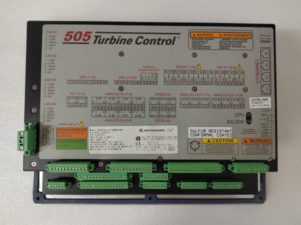
- Part Number: 8200-1300
- Input Voltage: 24 VDC nominal (18–32 VDC operating range)
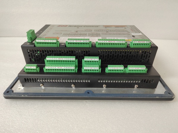
- Discrete Outputs: 2 Form-C relay outputs (rated 8 A at 240 VAC / 30 VDC)
- Analog Inputs: 4 configurable inputs (0–20 mA or 0–10 VDC)
- Analog Outputs: 2 configurable outputs (0–20 mA or 4–20 mA)
- Communications: RS-485 Modbus RTU, USB (for PC configuration)
- Operating Temperature: –40°C to +70°C (–40°F to 158°F)
- Isolation Rating: 1500 VAC between inputs/outputs and earth ground
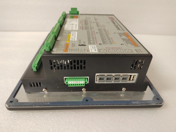
- Mounting: DIN-rail or panel mount
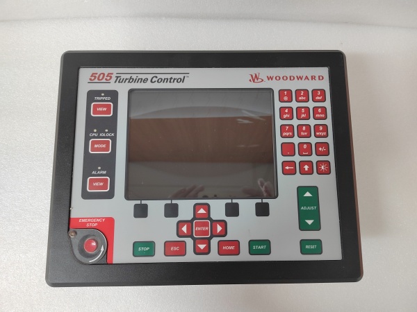
Woodward 8200-1300
The Real-World Problem It Solves
Getting multiple generators to play nice together in a black-start scenario or complex utility paralleling scheme is a nightmare. Without a dedicated load sharing controller, you get “fighting” governors, reverse power trips, and unstable frequency as each genset tries to assert its own speed curve.
Where you’ll typically find it:
- Mounted on the DIN rail of a 480V emergency standby generator control panel, directly behind the operator’s interface.
- Integrated into a microgrid switchgear lineup, communicating via Modbus RTU to a master PLC.
- Serving as the primary speed bias and load share node for a Woodward 2301D or easYgen system upgrade.
This module takes the guesswork out of droop and isochronous load sharing, providing a stable, programmable brain that keeps the kilowatts evenly distributed across the bus.
Hardware Architecture & Under-the-Hood Logic
The 8200-1300 is a dedicated single-board computer built to withstand the electromagnetic brutality of a generator switchgear room. It doesn’t mess around with fluff; it reads the bus, calculates the load, and sends a precise analog bias signal to the prime mover’s governor.
- High-Speed ADC Front End: The unit continuously samples its analog inputs (kW, PF, voltage) and digital status bits. Hardware filtering knocks down the electrical noise from adjacent contactors and SCR drives.
- PID Control Loop Execution: A dedicated microprocessor runs the load sharing and speed control algorithms. It compares the genset’s performance against the global bus frequency and the configured droop settings.
- Isolated Output Drive: Based on the PID calculation, the unit generates a 4–20 mA or 0–10 VDC bias signal. An onboard digital isolator ensures this control signal remains pure, even if the generator ground lifts several volts during a fault.
Field Service Pitfalls: What Rookies Get Wrong
Ground Loop Mayhem on the 4–20 mA Bias Line
A rookie wires the 4–20 mA output directly to the governor’s bias input using the same ground reference as the noisy generator exciter. As soon as the contactor slams shut, the bias signal gets so much noise that the governor starts hunting, causing the frequency to bounce wildly.
- Field Rule: Always use differentially isolated transmitters and receivers for your bias signals. Better yet, use the onboard isolation blocks and run a dedicated shielded twisted pair (STP) for the 4–20 mA line, grounding the shield at the DPC-II+ end only.
Ignoring the “Deadband” in Parallel Operation
Two identical gensets are running in parallel. One is sweating at 80% load while the other is loafing at 40%. The rookie checks the calibration, finds nothing wrong, and wastes three hours swapping sensors.
- Field Rule: Check the Deadband (or “Stability”) tuning parameter in the DPC software. If the deadband is set too wide, the controller won’t react to small load imbalances. Tighten the deadband incrementally until the loads balance, but watch your stability—if it starts oscillating, you’ve gone too far.
Woodward 8200-1300
Commercial Availability & Pricing Note
Please note: The listed price is for reference only and is not binding. Final pricing and terms are subject to negotiation based on current market conditions and availability.


