
Description
Hard-Numbers: Technical Specifications
- Part Number: 5453-277
- Compatible Modules: Accepts two (2) Woodward MicroNet power supply modules (e.g., 5400-series)
- Input Voltage: Dependent on installed AC/DC power modules (typically 90-264 VAC or 100-300 VDC wide range)
- Output Voltage: Dependent on modules (typically +24V DC, +5V DC, ±12V DC)
- Redundancy Mode: Load Sharing / Hot Standby
- Switchover Time: < 1 millisecond (seamless, zero system interruption)
- Operating Temperature: –20°C to +70°C (–4°F to 158°F)
- Cooling Method: Passive convection (chassis acts as heat sink)
- Mounting: 19-inch rack mount or panel mount
- Compliance: CE, UL, CSA
Woodward 5453-277
The Real-World Problem It Solves
In a turbine control panel, a simple power supply failure used to mean a forced outage or a dangerous trip. The 5453-277 chassis eliminates the single point of failure by allowing two power supplies to share the load; if one dies, the other picks up the slack instantly without the controller ever knowing.
Where you’ll typically find it:
- Mounted in the upper or lower rack of a gas compressor station control panel, keeping the MicroNet TMR CPU alive during site power fluctuations.
- Bolted into the back of a steam turbine skid enclosure, distributing clean DC power to the I/O modules and safety loops.
- Serving as the primary power backbone in offshore platform ESD (Emergency Shutdown) systems where reliability is measured in MTBF, not hours.
This chassis ensures your triple-redundant controller actually stays redundant, providing the hardware foundation required for SIL-rated safety loops and continuous process operation.
Hardware Architecture & Under-the-Hood Logic
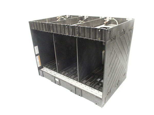
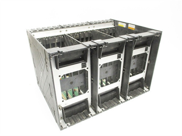
The 5453-277 is a passive, highly engineered backplane designed to host two independent power supply modules. It isn’t just a metal box with terminals; the internal busbars are designed to handle high inrush currents and provide strict isolation between the primary AC/DC inputs and the sensitive DC outputs.
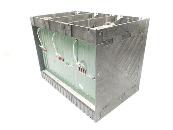
- Dual AC/DC Input Termination: The chassis provides robust terminal blocks for two independent incoming power sources (or one source split to two feeds). Massive copper traces ensure minimal voltage drop even at maximum rated load.
- Active Load Sharing Bus: When two power modules are installed, the chassis electronics facilitate active load balancing. Each module typically supplies 50% of the current, reducing thermal stress on the components and extending the operational lifespan of both units.
- Seamless Failover Logic: If Module A fails or is removed, the internal diodes and hold-up circuitry in the chassis prevent any reverse current flow. Module B instantaneously (within microseconds) ramps up to 100% capacity, maintaining a perfectly flat DC output waveform to the downstream MicroNet control modules.
Field Service Pitfalls: What Rookies Get Wrong
Mixing Old and New Power Modules
A rookie notices one of the two power supplies in the 5453-277 has failed. He grabs a brand-new module from the storeroom, pops it in, and suddenly the chassis starts overheating or the new module goes into constant fault mode.
- Field Rule: Never mix different hardware revisions or firmware versions of power modules in a single TMR chassis unless explicitly approved by Woodward’s compatibility matrix. The load-sharing algorithms can become unstable if the modules have different internal resistance or response times. Always replace modules in matched pairs if possible, or perform a full system load test after mixing batches.
Ignoring the Input Phase Balancing on Multi-Voltage Systems
The site electrician hooks up both 120VAC inputs to the same phase of the mains supply. A phase-to-phase short occurs elsewhere on the panel, blowing the main breaker and killing both power supplies in the 5453-277 simultaneously.
- Field Rule: If your MicroNet system requires high availability, always wire the two power supply inputs to differentupstream breakers or, ideally, entirely separate UPS systems. The chassis provides the redundant hardware; don’t negate it with a single-point failure at the wiring terminals. Label your drawings clearly: “PSU A – Breaker 1” and “PSU B – Breaker 2”.
Woodward 5453-277
Commercial Availability & Pricing Note
Please note: The listed price is for reference only and is not binding. Final pricing and terms are subject to negotiation based on current market conditions and availability.


