
Description
Key Technical Specifications
-
Model Number: 1720-719
-
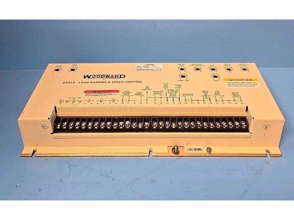
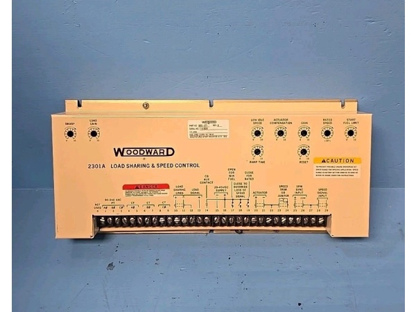
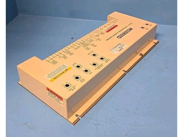
Manufacturer: Woodward Inc.
-
System Compatibility: ProTech-GII Overspeed Protection System (8237-1000/2000 series)
-
Input Types per Channel: 4-20mA (HART pass-through capable), 0-20mA, 0-10V, ±10V, 0-5V, ±5V, Type J/K/T/E/R/S/B/N thermocouples, 3-wire RTD (100Ω Pt)
-
A/D Conversion: 16-bit sigma-delta converter with 50/60Hz notch filtering
-
Accuracy: ±0.1% of full scale at 25°C (voltage/current); ±0.5°C (thermocouple, excluding sensor error)
-
Input Impedance: >1 MΩ (voltage ranges); 250Ω precision shunt (current ranges)
-
Bandwidth: 10 Hz (-3dB) with programmable digital filtering
-
Isolation: 1500Vrms continuous, 2500Vrms transient (1 minute) channel-to-channel and channel-to-backplane
-
Excitation Voltage: 24VDC loop supply available per channel (short-circuit protected)
-
Cold Junction Compensation: Internal CJC for thermocouples, ±0.5°C accuracy
-
Burnout Detection: Upscale/downscale configurable for 4-20mA inputs
-
HART Compatibility: FSK pass-through on 4-20mA channels for smart transmitter communication
-
Update Rate: 50ms standard, 100ms/250ms/500ms selectable for noise rejection
-
Operating Temperature: -40°C to +70°C
-
Storage Temperature: -40°C to +85°C
-
Humidity: 5% to 95% non-condensing
-
Certifications: SIL 2/SIL 3 capable (IEC 61508), marine certifications available

WOODWARD 9905-377
Field Application & Problem Solved
In the real world, overspeed protection isn’t just about RPM. A turbine can destroy itself without ever exceeding speed limits—low lube oil pressure, high bearing temperature, excessive vibration. The 1720-719 exists to bring those auxiliary process variables into the safety system loop. This matters because in many plants, these critical parameters live in the DCS or a separate Bently Nevada system, completely isolated from the overspeed trip logic. When seconds count, you don’t want to rely on a Modbus link or operator intervention.
You’ll find this module in any ProTech-GII installation where the turbine package demands integrated machinery protection. Steam turbines in combined-cycle plants use it to monitor bearing metal temperatures and lube oil header pressure. Gas turbines in pipeline compressor stations monitor vibration via proximity probe drivers (4-20mA output) and seal gas differential pressure. In hydro plants, it tracks wicket gate position feedback and penstock pressure. The common thread: these are process variables that need to trip the turbine, not just alarm it.
The core value is bringing auxiliary protection into the safety-rated architecture. Standard DCS analog inputs aren’t SIL-rated. They’re not fault-tolerant. They don’t have deterministic response times. The 1720-719 gives you safety-system integrity for process signals. Each channel is isolated—ground loops on your bearing temperature wiring won’t corrupt your lube pressure reading. The 16-bit resolution means you can actually see the difference between 15.9 and 16.0 mA, which matters when you’re trending bearing wear. And the 50ms update rate means if lube pressure crashes, the ProTech-GII sees it fast enough to trip before the bearings wipe.
Where this module earns its keep: HART pass-through. Your lube oil pressure transmitter is probably a smart device with diagnostic data—secondary variables, device status, drift alerts. The 1720-719 passes the HART FSK signal straight through to the ProTech-GII’s communication ports. You get your safety-rated 4-20mA for the trip function, plus full asset management data for predictive maintenance. I’ve used this to catch a transmitter approaching failure before it ever signaled a pressure problem. That’s the difference between scheduled maintenance and an emergency shutdown.
Installation & Maintenance Pitfalls (Expert Tips)
Loop Power vs. Externally Powered Transmitters
This module can power 4-20mA loops (24VDC supply), but don’t assume you should. If your transmitter is already powered by a separate 24V supply, wiring the 1720-719’s loop power in parallel creates a fight between power supplies. You’ll get erratic readings, possible module fault alarms, and in worst cases, a fried input channel. Check your loop diagrams. If the transmitter has its own power source, configure the channel for “passive” input (no loop power). The module detects this automatically on some revisions, but older firmware requires manual configuration in the ProTech-GII software. When in doubt, meter the line—if you see 24V with the field wires disconnected, don’t enable loop power.
Thermocouple Extension Wire: Match the Alloy
Thermocouples measure temperature at the junction, but they’ll measure temperature anywhere along the wire if you use the wrong extension cable. I’ve seen technicians run standard copper wire from a Type K thermocouple to the 1720-719. The module sees a junction at the terminal block—now you’re measuring cabinet air temperature, not bearing metal temperature. Use matched thermocouple extension wire (Type KX for Type K sensors) all the way to the module. The 1720-719 has internal cold junction compensation, but it assumes the terminal block is the reference junction. Copper wire defeats that assumption completely.
HART Multidrop: Know Your Limitations
Yes, the module passes HART, but it’s not a HART master. If you have three smart transmitters multidropped on one 4-20mA loop (common address 1, 2, 3), the 1720-719 will read the primary variable fine, but the ProTech-GII can’t poll individual device addresses. It sees the analog value only. For full HART device management, you need a separate HART multiplexer or handheld communicator on the line. Don’t expect the safety system to give you secondary variables from multidropped instruments—it won’t. Wire critical transmitters point-to-point if you need HART diagnostics in the ProTech-GII logs.
Filtering vs. Response Time Trade-off
The module offers digital filtering: None, Low, Medium, High. High filtering gives you rock-solid readings in electrically noisy environments, but it adds 500ms lag. On a lube oil pressure signal, that lag might be acceptable. On a vibration signal monitoring blade pass frequency, it’s useless—you’ll miss the event. I’ve seen plants default all channels to “High” filtering during commissioning to clean up noisy signals, then forget to tune them. Review your filtering settings against the process dynamics. Turbine bearing temperature changes slowly—use High filtering. Seal gas pressure during a compressor surge changes instantly—use None or Low.
Channel-to-Channel Isolation: Don’t Abuse It
The 1720-719 has 1500V isolation between channels. This is robust, but it’s not infinite. I’ve seen installations where someone grounded the negative side of Channel 1’s 4-20mA loop to the cabinet, and the negative side of Channel 2’s loop to a separate ground rod “for extra safety.” Now you’ve got a potential difference between channels. Under transient conditions (lightning strike, VFD switching), that potential can exceed 1500V and punch through the isolation barrier. Use a single-point ground reference for all analog signals. The isolation is there to protect against accidental faults, not to support fundamentally different grounding architectures.
RTD Wiring: The 3-Wire Assumption
The module supports 3-wire RTDs, but it assumes the two lead resistances are equal. If you run 100 feet of 18 AWG to the RTD using two conductors for one side and one for the other, the lead resistance imbalance introduces error. Use true 3-wire cable—two conductors to one terminal, one to the other, all identical gauge and length. Better yet, verify with a decade box at the RTD location. Inject 100.0Ω and confirm the module reads exactly 0°C (for Pt100). If it reads 2°C, you’ve got wiring resistance error that will skew your bearing temperature trip setpoints.
WOODWARD 9905-377
Technical Deep Dive & Overview
The 1720-719 is an analog input module designed to extend the ProTech-GII’s protection capabilities beyond speed sensing into full machinery protection. While the 1720-713 handles the life-safety-critical speed inputs, this module handles the process variables that determine whether the turbine survives the trip.
Each of the four channels is electrically isolated from the others and from the system backplane using magnetic isolation barriers. This is crucial in turbine applications where bearing temperature sensors might be referenced to rotating shaft potential, while pressure transmitters are grounded to the skid steel. Isolation prevents ground loops and common-mode voltage issues that plague standard PLC installations.
The input stage uses a multiplexer feeding individual sigma-delta A/D converters per channel. Sigma-delta architecture provides inherent noise rejection and high resolution, but it requires digital filtering to achieve the rated 16-bit performance. The module implements programmable finite impulse response (FIR) filters that trade bandwidth for noise rejection. At the “None” setting, you get 10Hz bandwidth with minimal latency. At “High,” the bandwidth drops to 0.5Hz but 60Hz electrical noise is suppressed by >60dB.
For 4-20mA inputs, the module uses precision 250Ω shunt resistors to convert current to voltage (1-5V range). The shunt is isolated from the measurement circuitry, allowing the loop to float at common-mode voltages up to ±250V relative to the module ground. Burnout detection monitors the loop current—if it drops below 3.6mA (configurable), the module flags a “Downscale Burnout” alarm. If it exceeds 21.0mA, it’s “Upscale Burnout.” This catches open or shorted field wiring before it causes a nuisance trip or missed alarm.
Thermocouple inputs route through the same A/D path but add internal cold junction compensation. A thermistor bonded to the terminal block measures ambient temperature at the connection point. The firmware applies the appropriate NIST polynomial correction for the thermocouple type (J, K, T, etc.) to calculate absolute temperature. Accuracy depends on the CJC thermistor tracking the actual terminal temperature—avoid mounting the module directly above heat-generating power supplies, as this creates a thermal gradient between the thermistor and the outer terminals.
HART pass-through is implemented via capacitive coupling. The 1200Hz/2200Hz FSK signal from the field device rides on the 4-20mA loop. The module passes this AC component through to the ProTech-GII’s HART modem port without loading the loop or affecting the DC measurement. This allows asset management software to communicate with field devices while the safety system maintains its independent analog monitoring.
Configuration is stored in non-volatile memory on the module. Each channel’s input type, range, filtering, and alarm setpoints download from the ProTech-GII CPU during initialization. If the module is swapped, it assumes default configuration until the CPU re-downloads parameters—typically 10-15 seconds after power-up. During this window, the module outputs “Bad Quality” status to prevent false trips based on unconfigured channels.
The module does not perform the trip logic locally—that’s handled by the main ProTech-GII processor. It provides the raw scaled engineering units (PSI, °C, mils) via the backplane bus. The CPU applies the programmed alarm and trip setpoints, implements voting logic between redundant sensors, and drives the trip relays. Response time from process change to trip relay action is typically 100-150ms, dominated by the CPU scan rate and the analog input filtering settings.


