
Description
Hard-Numbers: Technical Specifications
| Parameter | Specification |
|---|---|
| Manufacturer | Bosch Rexroth Indramat |
| Part Number | DDS02.1-W150-D |
| Series | DDS 2.1 (Series 2, Version 1) |
| Drive Type | Digital Intelligent AC Servo Drive |
| Rated Current | 150 A |
| Rated Voltage | 300 V (DC link) |
| Cooling Method | Internal air cooling (control cabinet external airflow) |
| Motor Feedback | Digital Servo Feedback (DSF) |
| Compatible Motors | INDRAMAT MDD, MKD, and LAR series AC servo motors |
| Communication Interfaces | SERCOS interface (fiber-optic) or Analog interface |
| Operating Temperature Range | 0°C to 45°C (rated data) / up to 55°C (derated) |
| Storage/Transport Temperature | -40°C to +70°C |
| Maximum Relative Humidity | 95% non-condensing |
| Maximum Absolute Humidity | 25 g/m³ |
| Protection Class | IP 10 (per DIN 40050) |
| Dimensions (H × W × D) | 39 cm × 31 cm × 11 cm (15.3 in × 12.2 in × 4.3 in) |
| Weight | 8.5 kg (18.7 lbs) |
| Power Supply Compatibility | 3 x AC 380-460 V, 50-60 Hz (via external power supply module) |
| Processor Type | Microprocessor-controlled (digital signal processor) |
| Position Control Loop Cycle Time | 0.250 ms (with SERCOS interface) |
| Position Resolution | 0.00001 mm to 180 m/min with linear scales (20 µm graticule) |
| Speed Resolution | 0.0001 rpm up to maximum speed |
| Output Frequency Range | Up to 504 kHz maximum |
| Mounting | Control cabinet installation (closed housing required) |
| Module Construction | Modular design (basic unit with function modules) |
| Communications Module | Factory assigned (plug-in card) |
| Function I.D. | Factory assigned |
| Function I.D. Version | Factory assigned |
| MPN | R911254330 |
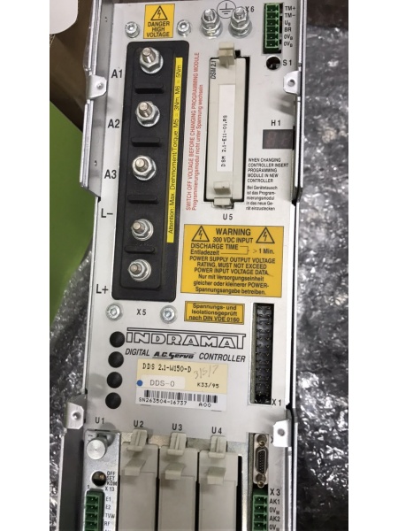
Rexroth DDS02.1-W150-D
The Real-World Problem It Solves
High-performance industrial automation demands precise, dynamic, and reliable servo control across multiple axes. The DDS02.1-W150-D delivers a 150A-rated output with digital servo feedback, enabling microprocessor-controlled brushless three-phase AC drives with exceptional dynamic response and precision. Its modular architecture supports SERCOS or analog interfaces, allowing seamless integration with CNC controls, NC systems, and PLCs—making it ideal for demanding applications like CNC machine tool axes, electronic transmissions, grinding machines, robots, handling systems, assembly equipment, woodworking machines, packaging machines, textile machines, and printing presses.
Where you’ll typically find it:
- CNC machining centers and grinding machines requiring nanometer-level precision
- Robotic workcells and handling systems with coordinated multi-axis motion
- High-speed printing presses and textile machinery with complex motion profiles
- Packaging machinery with rapid positioning and cycle times
- Woodworking equipment and bending machines with contouring requirements
- Assembly systems and roll-feed mechanisms with electronic transmissions
Bottom line: This is a digital intelligent AC servo drive designed for high-dynamic applications—offering 150A output capacity, digital feedback without additional wiring, modular flexibility, and the ability to exploit full digital drive capabilities when used with SERCOS interface, including high-resolution speed control, internal fine interpolation, and comprehensive diagnostics.
Hardware Architecture & Under-the-Hood Logic
The DDS02.1-W150-D is a digital intelligent AC servo drive controller based on the Indramat DIAX-02 architecture. It combines microprocessor control with modular construction to deliver precise three-phase AC motor control with digital servo feedback.
- Power Stage – Three-phase IGBT-based power inverter generating 150A rated output for AC servo motors (MDD/MKD/LAR series)
- DC Link Circuit – Internal DC bus (rated 300V) receiving power from external power supply module (3 x AC 380-460V input)
- Digital Signal Processor (DSP) – Microprocessor core executing servo control algorithms, position/velocity/current loops with 250µs cycle time
- Digital Servo Feedback (DSF) Interface – Digital encoder interface for rotor position measurement with extremely high resolution across entire speed range
- SERCOS Interface Module (optional) – Fiber-optic SERCOS communication for full digital integration with NC controls, enabling parameter display, diagnostics, and high-speed data exchange
- Analog Interface Module (optional) – Traditional analog ±10V command interface for velocity or torque control in legacy systems
- Module Slots – Plug-in module positions for communication modules (SERCOS/analog), function I.D. modules, and auxiliary options
- Control Circuitry – Digital monitoring and control logic for drive enable, fault detection, parameter storage, and diagnostic functions
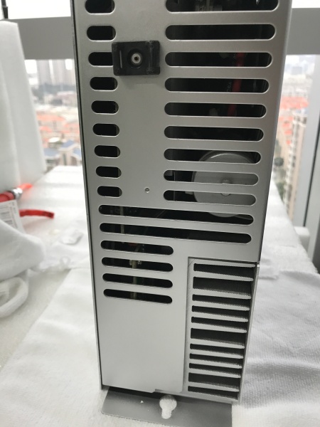
- Cooling System – Internal air cooling design requiring external cabinet airflow; heat dissipation through baseplate and internal heatsinks
- Terminal Block X1 – Main power connections for motor output phases (U, V, W) and braking resistor connections
- Terminal Block X2 – Control signal connections including enable inputs, fault outputs, and auxiliary I/O
- Terminal Block X3 – Encoder feedback connections (for motors with resolver or digital feedback)
- Terminal Block X4 – Auxiliary power and interface connections (24V logic supply, communication ports)
- Parameter Memory – Non-volatile storage for motor parameters, drive settings, and configuration data
- Diagnostic Buffer – Internal memory storing fault codes, error history, and status information for troubleshooting
- Display/Interface Port – VT-100 terminal interface for parameter display and entry (minimum requirement for analog interface configuration)
- Watchdog Timer – Hardware monitoring circuit detecting processor faults and triggering safe shutdown
- Overcurrent Protection – Fast-acting current limiting and fault detection protecting motor and drive
- Overtemperature Protection – Thermal sensors monitoring heatsink and power stage temperatures
- Brake Control – Integrated holding brake control output for motors with electromagnetic brakes
- Enable Logic – Two-channel enable circuitry requiring both enable inputs active for drive operation (safety function)
- Status Indicators – LED indicators for power, ready, fault, and communication status
- Fan (if equipped) – Optional forced-air cooling fan for high-power applications
- Grounding System – PE connections for safe operation and EMI suppression
- EMI Filter – Integrated filtering for electromagnetic interference suppression (EN 50081-2 compliance)
Rexroth DDS02.1-W150-D
Field Service Pitfalls: What Rookies Get Wrong
Ignoring Control Cabinet Airflow Requirements
DDS02.1-W150-D uses internal air cooling requiring external cabinet airflow. Rookies install drives in sealed cabinets without proper ventilation, causing overheating faults, thermal derating, or premature failure—especially at 150A rated current.
Field Rule: Ensure control cabinet provides adequate airflow for drive cooling. Calculate required airflow based on drive power dissipation (approximately 150W-200W plus motor regenerative power). Use cabinet fans or air conditioning for high-power installations. Monitor drive temperature during initial commissioning; if ambient temperature exceeds 45°C at rated current, consider derating or improving cooling.
Mismatching Motor Feedback Types
DDS02.1-W150-D with “-D” suffix supports digital servo feedback. Rookies attempt to connect resolver-based motors or analog encoders without proper feedback module compatibility, causing drive faults or erratic motor behavior.
Quick Fix: Verify motor encoder type before installation. “-D” suffix indicates digital servo feedback compatibility with Indramat MDD/MKD/LAR motors featuring digital encoders. For resolver feedback motors, ensure drive model has “-R” suffix or compatible resolver interface module. Check motor nameplate and drive model suffix match feedback type requirements.
Overlooking Enable Sequence Requirements
DDS02.1-W150-D requires proper two-channel enable sequence. Rookies apply only one enable signal or sequence enables incorrectly, resulting in drive not powering motor despite showing “ready” status.
Field Rule: Implement correct two-channel enable logic: Enable 1 and Enable 2 must both be active for drive to power motor. Sequence typically: (1) Power up drive, (2) Apply Enable 1, (3) Verify “ready” LED, (4) Apply Enable 2, (5) Verify drive status shows “operation”. Fault diagnosis: if only one enable active, drive will remain in “ready” but not power motor.
Neglecting DC Link Precharge Time
External power supply modules require DC link precharge before DDS drive enables. Rookies apply drive enable immediately after power-up, causing DC link voltage spikes, fault trips, or drive damage.
Quick Fix: Allow DC link precharge time (typically 500ms-2 seconds) after power supply enable before applying drive enable signals. Monitor DC link voltage via diagnostic software or multimeter if accessible; wait until voltage stabilizes at rated 300V before enabling drive. Precharge circuit protection prevents drive damage from inrush currents.
Incorrect Motor Phase Connections
Rookies swap motor phase connections (U-V-W) when replacing drives or motors, causing motors to rotate in wrong direction or exhibit unstable control (hunting, oscillation). Drive may trigger “phasing error” fault or “motor overload” alarms.
Field Rule: Always verify motor phase labeling before connection. If direction is incorrect, swap any two motor phases (e.g., U and V) after initial test—not during initial installation. For MDD/MKD motors, standard rotation direction is clockwise viewing from shaft end when phases connected U-V-W sequence. Document phase orientation during installation to prevent future confusion.
Misconfiguring SERCOS vs. Analog Interface
DDS02.1-W150-D supports both SERCOS and analog interfaces via plug-in modules. Rookies attempt SERCOS communication with analog module installed (or vice versa), causing communication failures or no response from drive.
Quick Fix: Identify installed communication module via module label or drive parameters. SERCOS module requires fiber-optic cable connection to NC control; analog module uses ±10V velocity/torque command signals via terminal block X2. Parameter configuration differs significantly between modes—SERCOS enables full digital diagnostics while analog mode requires VT-100 terminal for parameter access.
Forgetting to Configure Motor Parameters
DDS02.1-W150-D requires motor-specific parameters (current limit, speed, encoder resolution, thermal limits) before operation. Rookies run drive with default parameters, causing “parameter mismatch” faults or inadequate motor performance (stall, hunting, overheating).
Field Rule: Always configure motor parameters from motor nameplate data before first enable. Critical parameters: rated current, rated speed, encoder resolution, pole pairs, thermal time constant. Use VT-100 terminal or SERCOS interface to enter parameters via diagnostic software. Save parameters to non-volatile memory after configuration—document parameters for future reference.
Ignoring Braking Resistor Requirements
During deceleration or axis lowering, motor regenerates energy into DC link. Rookies operate drives without braking resistors on axes with high inertia or frequent stopping, causing DC link overvoltage faults and drive shutdowns.
Quick Fix: Install braking resistor sized for application regenerative energy (calculate based on axis inertia, deceleration rate, duty cycle). Connect braking resistor to designated terminals on drive power stage. Ensure braking resistor has adequate thermal rating and airflow. Test deceleration profiles and monitor DC link voltage; if overvoltage occurs, increase braking resistor wattage or reduce deceleration rates.
Misdiagnosing Fault Codes
DDS02.1-W150-D displays fault codes via LEDs and diagnostic buffer. Rookies misinterpret fault codes, replacing components unnecessarily—treating “overcurrent” faults as drive failures when caused by mechanical jams or motor shorts.
Field Rule: Use diagnostic buffer (VT-100 or SERCOS) to retrieve specific fault codes before component replacement. Common faults: F0xx (overcurrent), F1xx (overvoltage), F2xx (undervoltage), F3xx (overtemperature), F4xx (encoder faults), F5xx (communication faults). Check mechanical system before condemning drive—seized bearings, cable shorts, or brake malfunctions often cause drive faults.
Improper Grounding and Shielding
High-frequency switching in IGBT power stage generates EMI. Rookies neglect proper grounding and cable shielding, causing erratic encoder signals, communication interference, or unexpected fault behavior.
Quick Fix: Ensure PE connections are solid—use star grounding point if multiple drives share ground. Shield motor power cables (braid or foil) with grounded shield at drive end only (prevent ground loops). Shield encoder cables with shield grounded at drive end. Route signal cables away from power cables. Use ferrite cores on encoder cables if interference persists. Ground cabinet properly to building earth.
Neglecting Firmware/Parameter Backup
DDS02.1-W150-D stores parameters in non-volatile memory. Rookies replace drives without backing up parameters, losing critical configuration—causing extended downtime during recommissioning.
Field Rule: Before any drive replacement, use VT-100 terminal or SERCOS diagnostic software to read and document all parameters. Save parameter file to external storage or network share. After installing replacement drive, reload parameters and verify operation. Keep parameter backup for each axis in maintenance records—significant time savings during future service events.
Commercial Availability & Pricing Note
Please note: The listed prices are for reference only and are not binding. Final pricing and terms are subject to negotiation based on current market conditions, product condition (new vs. refurbished), and supplier.


