
Description
Hard-Numbers: Technical Specifications
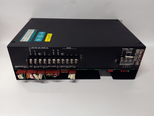
- Input Voltage: 100-240 VAC (universal input)
- Phase Configuration: Single-phase
- Line Frequency: 50/60 Hz
- Continuous Current Rating: 10A
- Peak Current Rating: 20A
- DC Bus Voltage: 141-340 VDC (325 VDC at 230 VAC input)
- Command Signal Range: ±10 VDC
- Command Input Impedance: 13.3 kΩ
- Continuous Shunt Power: 50W
- Peak Shunt Power: 4.5 kW
- Dissipative Shunt Max Loss: 100W
- Weight: 15 lbs (6.8 kg)
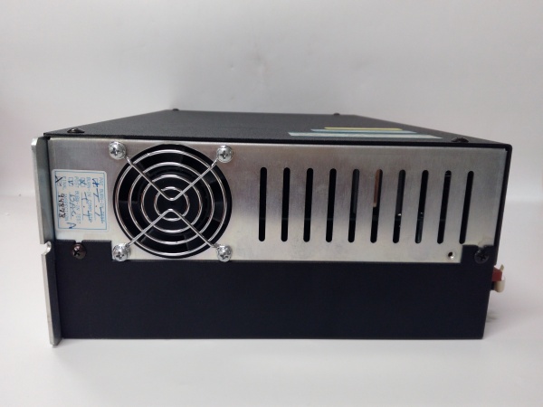
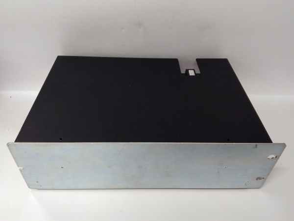
- Enclosure Type: Open chassis style with integrated cooling fan
- Operating Temperature: 32-122°F storage (extended range in operation)
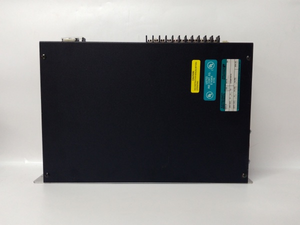
- Diagnostic Interface: 4 LED indicators (1 green status, 3 red fault)

RELIANCE DM-20D
The Real-World Problem It Solves
Machine retrofits and legacy automation systems need reliable servo control without completely replacing existing motion architectures. The DM-20D bridges older Electro-Craft motor platforms with modern control requirements, delivering precise position and torque control through a compact 20A amplifier that fits standard cabinet footprints.
Where you’ll typically find it:
- CNC machining centers and retrofitted machine tools
- Packaging machinery with motion-controlled axes
- Material handling systems and conveyor positioning
- Automated assembly equipment with brushless servo axes
Bottom line: It’s a workhorse 20A servo amplifier that keeps legacy Electro-Craft motion systems running reliably where full system replacement isn’t economically justified.
Hardware Architecture & Under-the-Hood Logic
The DM-20D is a single-phase brushless servo drive amplifier designed to convert line voltage into controlled three-phase PWM power for Electro-Craft brushless motors. It operates as a power amplifier stage receiving low-level command signals from external controllers and delivering high-current motor phase outputs based on commutation logic.
- Single-phase AC input (100-240V) enters the drive and passes through EMI filtering
- Input rectifier stage converts AC to DC, establishing the internal DC bus (141-340 VDC)
- DC bus capacitors smooth the rectified voltage and provide energy storage for motor current demands
- IGBT (or MOSFET) power switching stage inverts DC bus voltage into three-phase PWM output
- Commutation logic reads encoder feedback from motor (via P4 connector) to determine rotor position
- Command signal (±10V analog from P1 controller port) sets torque or velocity reference
- Current feedback loops monitor motor phase currents and adjust PWM duty cycle for closed-loop control
- Output stage delivers controlled three-phase power to motor phases through TB1 terminal block
- Regenerative braking energy dissipated through internal shunt resistor (50W continuous, 4.5kW peak)
- Internal fan pulls air through chassis vents, cooling power semiconductors during operation
RELIANCE DM-20D
Field Service Pitfalls: What Rookies Get Wrong
Mismatched Motor PairingThe DM-20D is specifically engineered for Electro-Craft F-Series and S-Series motors (F-4030, S-4030, S-3016). Newbies try to drive random brushless motors with it, expecting universal compatibility like modern VFDs.
Field Rule: Verify motor compatibility before installation. Only use Electro-Craft F-Series or S-Series motors rated for the DM-20D’s current output. Cross-reference motor nameplate voltage and continuous current against drive specifications (10A continuous, 20A peak).
Ignoring Peak vs Continuous Current RatingsTechnicians size applications based on the 20A peak rating instead of the 10A continuous rating. The drive will run for minutes or hours then fault on thermal overload when the application demands sustained high current.
Quick Fix: Calculate the RMS current requirement for your motion profile. If your application draws more than 10A continuously, you need a larger drive or reduce the load/cycle time. Use the 20A peak rating only for short acceleration/deceleration transients.
Poor Encoder Cable ShieldingThe P4 motor encoder connector carries low-level position feedback signals. Improperly grounded or unshielded encoder cables introduce noise that causes erratic motion, hunting, or position error faults.
Field Rule: Use double-shielded encoder cables with the drain wire tied to the chassis ground at the drive end only. Keep encoder cables separated from high-power motor power cables by at least 6 inches to prevent coupling noise into the feedback loop.
Incorrect Command Signal GroundingThe ±10V command signal enters through the P1 controller port. Newbies ground the command signal at both the controller and drive end, creating ground loops that cause offset errors or unexpected motion.
Quick Fix: Ground the command signal common at the controller source only. Use an isolated signal conditioner if your controller ground reference differs significantly from the DM-20D ground potential. Verify the command signal with a multimeter before connecting to the drive.
Neglecting DC Bus Pre-ChargeAfter power-down, the DC bus capacitors hold lethal voltage for several minutes. Technicians reach inside the chassis immediately after disconnecting line power, risking shock or damaging components with test probes.
Field Rule: Always wait at least 5 minutes after power-off before touching internal components. Measure DC bus voltage across the main capacitors using a properly rated meter. Verify voltage has discharged below 50V before any maintenance work.
Overlooking Shunt Resistor CoolingThe internal braking shunt dissipates up to 4.5kW during deceleration. Installing the drive in sealed cabinets without airflow causes the shunt resistor to overheat and fail during frequent start-终止 cycles.
Quick Fix: Ensure adequate cabinet ventilation or force-air cooling around the DM-20D chassis. Calculate regenerative energy from your load profile—if applications involve frequent high-inertia deceleration, consider external braking resistor options to extend drive life.
Please note: The listed price is for reference only and is not binding. Final pricing and terms are subject to negotiation based on current market conditions and availability.


