
Description
Hard-Numbers: Technical Specifications
- Input Voltage: 115 VAC or 230 VAC (selectable via internal jumper)
- Line Frequency: 50/60 Hz
- Output Voltage: +24 VDC ±1%
- Output Current: 3.0 A continuous, 4.0 A peak (<5 seconds)
- Output Power: 72W continuous
- Efficiency: ≥85% (typical)
- Output Ripple Noise: <50 mVpp
- Hold-up Time: Several milliseconds (ensures safe shutdown during power loss)
- Protection Functions: Short-circuit (auto-recover), Overload (120% for 10 sec triggers hiccup mode), Over-voltage/Under-voltage (±15% threshold), Over-temperature (>85°C)
- Operating Temperature: 0°C to +60°C
- Humidity: 95% RH (non-condensing)
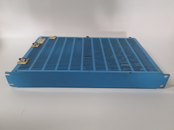
- Mounting: DIN rail or panel screw mount (front-access plug-in design)
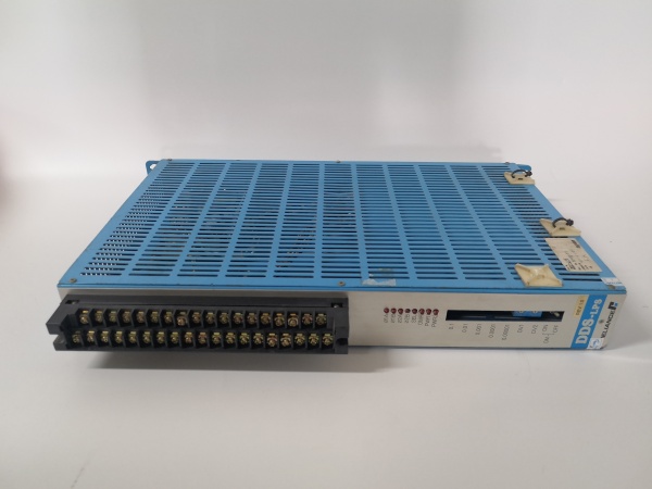
- Status Indicator: 1× Green LED (Power OK)
- Certifications: UL 508, CSA C22.2, CE

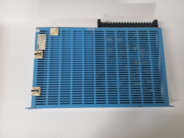
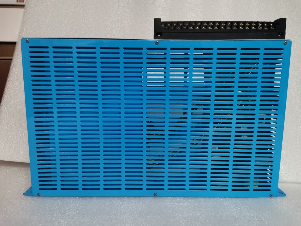
RELIANCE ELECTRIC DDS-LPS
The Real-World Problem It Solves
Digital DC drives require ultra-clean logic power to maintain precise speed regulation and current feedback accuracy in environments saturated with SCR switching noise and EMI. The DDS-LPS delivers isolated 24VDC with medical-grade stability, preventing control board glitches that could cause catastrophic thyristor misfiring or uncontrolled motor acceleration in critical drive systems.
Where you’ll typically find it:
- Steel mill hot rolling mills powering DDS-700 drives for main stand motors
- Mining hoist systems with DDS-500 drives controlling winding drums
- Paper machine reel and winder sections requiring precise tension control
- Cement kiln main drives and marine propulsion auxiliary systems
- Legacy retrofit projects maintaining original DDS drive architectures
Bottom line: It’s the heartbeat of DDS drive control logic—failsafe, low-noise power that keeps thyristor firing accurate when the difference between controlled steel rolling and a wrecked coil comes down to millivolts on the control rail.
Hardware Architecture & Under-the-Hood Logic
The DDS-LPS is a high-frequency switch-mode power supply purpose-built for Reliance DDS drive control platforms. It converts line AC into tightly regulated 24VDC through multi-stage conversion with active filtering, delivering clean power to sensitive microprocessor boards, gate firing circuits, and encoder feedback interfaces that cannot tolerate ripple or noise from the main drive power stage.
- AC input (115V or 230V) enters through EMI filter to suppress incoming line noise
- Input voltage selection via internal jumper configures the front-end rectification stage
- Bridge rectifier converts AC to unregulated DC for the switching stage
- High-frequency PWM switching controller (likely 50kHz+ based on topology) drives power MOSFETs
- Power MOSFETs chop DC into high-frequency AC for the isolation transformer
- Isolation transformer steps down voltage and provides safety isolation from line
- Secondary rectification converts transformer output back to DC
- Output LC filter (inductor + capacitors) smoothes the 24VDC output
- Precision voltage regulator maintains ±1% tolerance regardless of load variations
- Current sense circuits monitor output current and trigger protection at 120% overload
- Thermal sensor monitors internal temperature; shuts down if exceeding 85°C
- Hold-up capacitor bank provides several milliseconds of power during input voltage dips
- Green “Power OK” LED illuminates when all output parameters are within spec
- Output connectors distribute 24VDC to drive control boards via dedicated wiring harness
RELIANCE ELECTRIC DDS-LPS
Field Service Pitfalls: What Rookies Get Wrong
Incorrect Input Voltage Jumper SettingThe DDS-LPS supports both 115VAC and 230VAC input via internal jumper. Newbies skip verifying this setting before energizing, applying 230V to a board configured for 115V and instantly destroying the input stage components.
Field Rule: Always open the module cover and verify the input jumper matches your site voltage before installation. Use a multimeter to confirm line voltage at the terminal block. Never assume the jumper position is correct—surplus and refurbished units often come misconfigured.
Ignoring DC Bus Discharge TimeDDS drives store lethal energy in the DC bus capacitors for minutes after power-off. Techicians reach into the cabinet immediately after shutting off the main breaker, risking shock or damaging the DDS-LPS when probing live circuits.
Quick Fix: Wait at least 10 minutes after main power disconnect before servicing. Measure DC bus voltage across the main capacitors with a properly rated meter. Verify voltage has discharged below 50V before touching any DDS components, including the DDS-LPS.
Loose Connector Engagement on Front-Access InstallationThe DDS-LPS plugs into the DDS drive motherboard via a dedicated connector. Newbies don’t fully seat this connection before tightening the mounting screws, causing intermittent contact that triggers random drive faults or control board resets.
Field Rule: Align the DDS-LPS connector with the motherboard socket and push firmly until you feel positive engagement. Verify no gap remains between module backplane and drive chassis. Only then tighten the two mounting screws in a cross pattern to ensure even pressure.
Overlooking Ripple Noise on Analog Feedback SignalsThe DDS-LPS output powers encoder feedback and current sensing circuits. Using excessively long or unshielded 24V wiring picks up SCR switching noise, causing jitter in speed feedback and unstable current regulation on the drive.
Quick Fix: Use twisted-pair shielded cable for 24V distribution from DDS-LPS to sensitive analog circuits. Ground the shield at the DDS-LPS end only. Keep 24V logic wiring separated from high-power motor and armature cables by at least 6 inches to prevent noise coupling.
Neglecting Green LED Status During Routine InspectionThe front-panel “Power OK” LED provides immediate health indication. Newbies ignore this indicator during walkthroughs, missing early warning signs of impending failure like dimming or flickering that precede complete shutdown.
Field Rule: Include DDS-LPS LED status in your daily PM checklist. A solid bright green means healthy. Dim, flickering, or extinguished LED (with input power present) indicates degraded capacitors, failing regulator, or thermal stress—schedule replacement before the drive faults offline.
Underestimating Hold-Up Time RequirementsThe DDS-LPS hold-up capacitors maintain logic power during brief input interruptions. In facilities with unstable grid power, degraded capacitors fail to provide this bridge, causing the drive control logic to reset during voltage sags and triggering nuisance faults.
Quick Fix: Monitor site power quality with a power quality recorder. If frequent voltage dips or sags occur, consider adding external UPS or line conditioner before the DDS drive cabinet. Replace DDS-LPS units older than 8-10 years proactively as capacitor electrolyte dries out, reducing hold-up capacity.
Please note: The listed price is for reference only and is not binding. Final pricing and terms are subject to negotiation based on current market conditions and availability.


