
Description
Hard-Numbers: Technical Specifications
-
Channels: 1 analog input (2 ADCs interleaved on same channel)
-
ADC Resolution: 8 bits
-
Sampling Rate: 3 GS/s (effective, via interleaved dual 1.5 GS/s ADCs)
-
Input Bandwidth: DC to 1000 MHz (-3 dB, typical)
-
Input Impedance: 50 Ω (DC coupled, terminated)
-
Input Ranges: 125 mV, 250 mV, 500 mV, 1V, 2V (software selectable, full-scale)
-
DC Accuracy: ±5% of full scale (all ranges)
-
Onboard Memory: 512M to 2G samples (dual-port buffer, acquisition continues during transfer)
-
Bus Interface: PCI Express x1 (Gen1, 2.5 GT/s)
-
Trigger Sources: Software, external BNC (TRIG IN), internal TTL, quadrature encoder
-
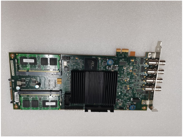
I/O Connectors:
-
BNC: CH A (signal input)
-
BNC: CH B (second input, used in 2-channel config or interleaving)
-
BNC: TRIG IN/TRIG OUT
-
BNC: Clock (external reference)
-
-
Power Requirements: +5V @ 3.5A, +3.3V @ 2.4A, +12V @ 0.01A, -12V @ 0.01A
-
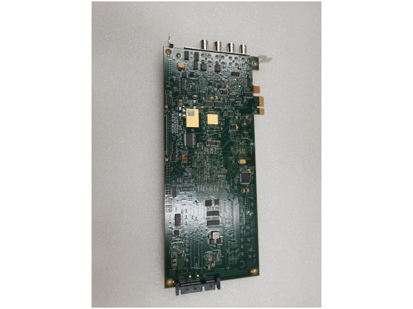
Physical: Single-slot PCIe card, 4.25″ x 9.375″ (107mm x 238mm), 210g
-
Operating Temperature: 0°C to +55°C
-
Storage Temperature: -20°C to +70°C
-
Relative Humidity: 5% to 95% (non-condensing)

AL8XGTE-3
The Real-World Problem It Solves
Ultrasonic NDT and acoustic microscopy need to capture 10-50 MHz transducer signals with enough resolution to see micro-defects. A 10 MHz signal needs 40-50 MHz sampling minimum (Nyquist + margin), but to see phase shifts and small amplitude variations, you want 100 MHz or more. When you’re scanning a BGA package for delamination or checking weld integrity, you can’t afford to miss a 50 ns transient. The AL8XGTE-3 gives you 3 GS/s—300x oversampling on a 10 MHz signal—so you see every wiggle in the waveform. And unlike a benchtop scope, it streams deep records (2G samples) to PC memory via PCIe without gaps.
Where you’ll typically find it:
-
Scanning Acoustic Microscopes (SAM): OKOS/SONIX/PVA TePla systems inspecting IC packages, MEMS, and bonded structures for voids and delamination.
-
Ultrasonic NDT scanners: Multi-axis immersion tanks checking aerospace composites; the digitizer captures A-scans at each XY position.
-
Research labs: Materials science setups studying acoustic emission, where 3 GS/s catches the initial transient of crack propagation.
Bottom line: It’s the front end of an acoustic microscope or NDT system, turning ultrasonic echoes into digital data without the $50K price tag of a high-end scope.
Hardware Architecture & Under-the-Hood Logic
This board uses interleaved sampling to hit 3 GS/s with affordable ADCs. Two 8-bit, 1.5 GS/s ADCs sample the same input signal 180 degrees out of phase; the FPGA interleaves the samples to create a 3 GS/s stream. The analog front end is DC-coupled and 50 Ω terminated—no AC coupling option, so plan your biasing accordingly.
-
Analog input: BNC CH A → attenuator/amplifier (software-selectable gain) → anti-alias filter → splitter to ADC A and ADC B.
-
Interleaved sampling: ADC A samples at 0°, 240°, 480°… ADC B samples at 180°, 420°, 660°… FPGA combines into single 3 GS/s data stream.
-
Memory buffer: Dual-port SRAM allows simultaneous write (from ADCs) and read (to PCIe DMA). Buffer depth 512M-2G samples depending on option.
-
Trigger system: External TRIG IN (TTL threshold) or software trigger arms acquisition. Pre-trigger and post-trigger recording available.
-
Data transfer: PCIe x1 DMA engine streams to host PC memory. Sustained throughput ~200 MB/s (limited by PCIe x1), so 3 GS/s × 1 byte = 3 GB/s—you cannot stream continuous 3 GS/s to PC. You must use onboard memory for high-speed bursts, then transfer after acquisition.
AL8XGTE-3
Field Service Pitfalls: What Rookies Get Wrong
Assuming Continuous Streaming at 3 GS/s
The PCIe x1 interface tops out around 200 MB/s. At 3 GS/s × 8 bits = 3 GB/s, you’ll overwhelm the bus in 70 milliseconds. Rookies set up “continuous” acquisition and wonder why they get buffer overruns or truncated data.
-
Field Rule: This is a burst digitizer, not a streaming digitizer. Use onboard memory (512M-2G samples) to capture your event at 3 GS/s, then transfer to PC after trigger. Max record length at 3 GS/s: 512M samples = 170 ms, 2G samples = 667 ms. For longer events, drop sample rate or use multiple record mode (segmented acquisition). If you need true streaming, look at PCIe x8 or x16 digitizers like the NI PXIe-5186.
Ignoring Interleave Spurious Artifacts
Dual-ADC interleaving creates artifacts. If the two ADCs have slightly different offset or gain (even 0.5%), you see spurious tones at fs/2 (1.5 GHz) and its harmonics in your FFT. A “clean” 500 MHz sine wave shows ghosts at 1.0 GHz and 2.0 GHz.
-
Quick Fix: Run the built-in calibration routine in OKOS software (AL8xGTe Calibrate) to match ADC offsets. Check for temperature drift—interleave accuracy degrades >10°C from calibration temp. If artifacts persist, one ADC may be failing; swap to single-ADC mode (1.5 GS/s) to isolate which channel is bad. For critical measurements, dither the input slightly or use single-ADC mode and accept lower sample rate.
Forgetting the 50 Ω Termination Requirement
The input is DC-coupled 50 Ω. Connect a high-impedance scope probe or unterminated cable, and you get reflections, ringing, and amplitude errors. Worse, if your source is 50 Ω output but AC-coupled, the DC bias current through the AL8XGTE-3’s termination resistor (if any) can saturate the front end.
-
Field Rule: Always use 50 Ω coax (RG-58, RG-174, or better) and terminate the source if it’s not already 50 Ω output. If you must use a 10× scope probe, add a 50 Ω feedthrough termination at the BNC to maintain impedance. Check DC offset at the BNC with a DMM before connecting—if you see >±2V DC, add a DC block (capacitive coupling) or risk damaging the front-end op-amps. The input protection is ±5V max; a charged coax from a piezo transducer can hit 50V—use external clamping diodes or a protection pad.


