
Description
Hard-Numbers: Technical Specifications
- Listing Standards: UL 864 9th Edition, ULC-S527-11
- Intelligent Signaling Line Circuits (SLC) : 1 expandable to 2 (Style 4, 6, or 7)
- Devices per SLC: Up to 159 detectors + 159 modules per loop (318 per loop/636 per FACP)
- SLC Polling Time: Less than 2 seconds for 318 devices
- Activation Time: Up to 159 outputs in less than 5 seconds
- Notification Appliance Circuits (NAC) : 4 built-in, Class A/B selectable, 1.5 A each
- Total Power Output: 6.0 A in alarm (3.0 A standby from integral CPS-24 power supply)
- Relay Outputs: Built-in Alarm, Trouble, Supervisory, and Security relays
- Display: 80-character programmable LCD (KDM-R2) or 640-character NCA-2 network annunciator
- Sensing Technology: ONYX intelligent sensing with 9 sensitivity levels, drift compensation
- Sensitivity Windows: Ion (0.5-2.5%/ft), Photo (0.5-2.35%/ft), Laser (0.02-2.0%/ft)
- Auto Detector Testing: NFPA-72 compliant automatic testing
- Network Capacity: Up to 103 nodes (standard) or 200 nodes (high-speed network)
- History Log: 800 events nonvolatile + 200-event alarm-only file
- Remote Annunciators: Up to 32 (80-character)
- Input Power: CPU2-640 (120 VAC, 5.0 A), CPU2-640E (220-240 VAC, 2.5 A)
- Frequency: 50/60 Hz
- Battery Charger: 18-200 AH sealed lead-acid, float voltage 27.6 V
- Operating Temperature: 0-49°C (32-120°F)
- Operating Humidity: 93% ±2% RH non-condensing at 32°C ±2°C (90°F ±3°F)
- Approvals: Marine approved, seismic certified
- Weight: 14.3 lb (6.49 kg) for CPU2-640, 14.55 lb (6.60 kg) for CPU2-640E
- Dimensions: Mounts in CHS2-M2 chassis; cabinet sizes vary per CAB-4 series

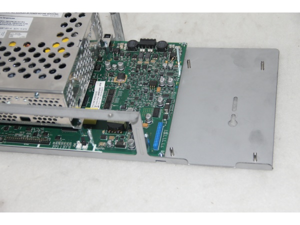
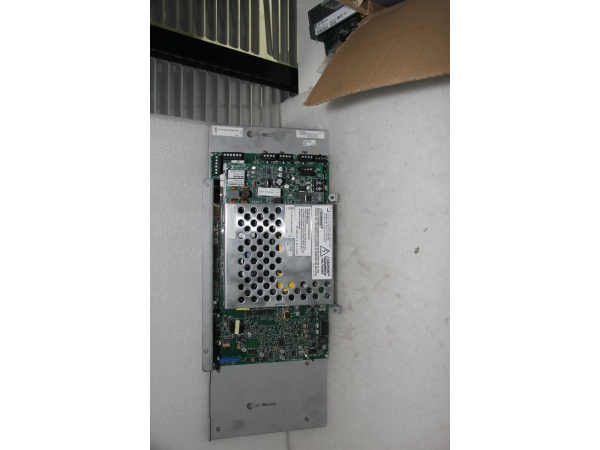
Notifier CPU2-640
The Real-World Problem It Solves
When you need a fire alarm system that scales from small buildings to large campuses while maintaining precise detection and reliable notification, this modular panel provides intelligent addressable capability without the complexity of larger chassis systems. The FlashScan protocol delivers fast polling and output activation, meeting code requirements for high-occupancy applications.
Where you’ll typically find it:
- Commercial office buildings requiring addressable detection
- High-rise structures with complex notification routing
- Industrial facilities with harsh environment detection needs
- Campus-wide networks integrating multiple buildings
- Marine applications requiring seismic and marine approvals
Bottom line: It delivers UL 864-compliant fire protection in a modular package that expands from single-panel systems to multi-node networks, maintaining 6.0 A power output and intelligent sensing throughout.
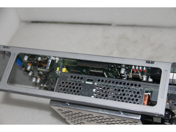
Hardware Architecture & Under-the-Hood Logic
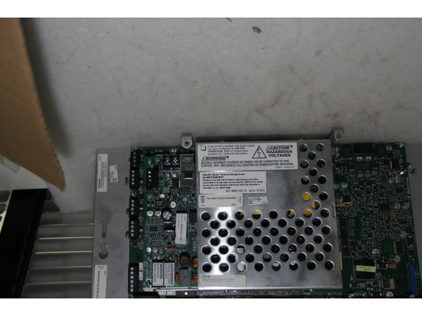
The CPU2-640 centers on a microprocessor-based fire alarm controller with integral CPS-24 switching power supply. One or two intelligent SLC loops communicate with addressable devices using FlashScan protocol. Built-in NAC circuits, relay outputs, and optional network interfaces complete the system architecture.
Signal flow and processing logic:
- Power Input: AC input (120/240 VAC) powers integral CPS-24 supply with battery charger.
- CPS-24 Power Supply: Delivers 3.0 A standby, 6.0 A alarm power to all internal circuits.
- Microprocessor: CPU executes FlashScan protocol, polling devices and managing system logic.
- Intelligent SLC Loops: Addressable detectors and modules communicate via isolated signaling lines.
- FlashScan Protocol: Polls 318 devices in under 2 seconds; activates 159 outputs in under 5 seconds.
- NAC Circuits: Four built-in notification circuits (1.5 A each) drive horns, strobes, speakers.
- Relay Outputs: Alarm, Trouble, Supervisory, and Security relays interface with external systems.
- Display Interface: KDM-R2 80-character LCD or NCA-2 640-character annunciator shows system status.
- Network Interface: Optional NCM or HS-NCM enables multi-panel networking up to 103/200 nodes.
- Battery Backup: 18-200 AH batteries provide standby power per UL 2610 requirements.
Notifier CPU2-640
Field Service Pitfalls: What Rookies Get Wrong
Overlooking Degraded Mode Configuration
The Disable/Enable switches on NAC circuits control degraded mode operation. If CPU microprocessor fails, FlashScan detectors can still activate NAC outputs—but only if these switches are enabled.
- Field Rule: Verify all four NAC degraded mode switches are in Enable position during commissioning. During testing, temporarily disable one circuit to verify degraded mode function. If the CPU fails and degraded mode is disabled, detectors cannot activate notification circuits even during an actual fire.
Incorrect End-of-Line Resistor Wiring
Class A and Class B circuits require different EOL resistor configurations. Techs wire Class B EOL resistors at the last device when Class A requires wiring at the last device and loop-back to the panel.
- Quick Fix: Confirm circuit style in system programming before wiring. Class B: EOL at last device only. Class A: EOL at last device plus wire returning to panel. Use supplied ELR-2.2K resistors only. Incorrect EOL wiring causes immediate trouble conditions and prevents circuit supervision.
Ignoring Power Budget Calculations
The 6.0 A total power budget is shared by all circuits. Adding NAC expanders, auxiliary modules, or remote annunciators without recalculating current draw causes brownouts during alarm conditions.
- Field Rule: Use the installation manual current calculation sheet before adding any peripheral. Sum standby and alarm currents for all devices. Ensure standby current does not exceed 3.0 A and alarm current does not exceed 6.0 A. For batteries over 26 AH, use separate cabinet per code requirements.
Miswiring SLC Isolator Bases
B224BI isolator bases prevent short circuits on SLC loops but must be installed correctly. Reversing polarity or missing the isolator jumpers causes entire loop failure.
- Field Rule: Verify isolator base orientation—red indicator faces the panel direction. Ensure base jumpers are installed per loop wiring diagrams. Test loop continuity by temporarily removing power and measuring resistance between SLC terminals. Isolators should not affect total loop resistance when correctly installed.
Neglecting Auto-Programming Validation
Autoprogramming speeds installation but loads devices with default parameters. Techs accept defaults without verifying detector types and sensitivity settings for the specific application.
- Field Rule: Run Autoprogramming, then manually verify each device entry. Confirm detector type (ion, photo, thermal, multi-sensor), sensitivity level, and pre-alarm settings match the application environment. High-ceiling spaces require different sensitivity than office areas. Document all deviations from defaults in the as-built drawings.
Improper NAC Circuit Loading
Each NAC circuit provides 1.5 A maximum. Connecting strobes with high inrush current without accounting for strobe synchronization causes nuisance trips during alarm activation.
- Field Rule: Calculate total steady-state current per NAC circuit including inrush. Select System Sensor, Wheelock, or Gentex synchronization protocol matching the installed appliances. Verify total current per circuit stays under 1.5 A. Use NAC expansion modules (APS-6R) for additional circuits rather than overloading built-in outputs.
Skipping VeriFire Tools Program Validation
Panel programming from the keypad works, but VeriFire Tools provides program check, compare, and simulate functions. Techs program directly without running these verification steps.
- Field Rule: Always upload panel database to VeriFire Tools before final acceptance. Run program check for errors, compare with design documents, and simulate alarm conditions. This catches missing cross-zone logic, incorrect NAC mappings, and unprogrammed detector addresses that keypad programming might miss.


