
Description
Hard-Numbers: Technical Specifications
-
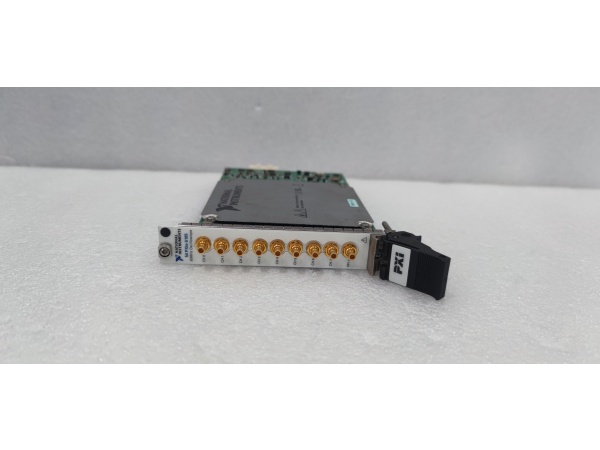
Channels: 8 analog inputs, simultaneously sampled
-
ADC Resolution: 12 bits (effective 10.5 bits typical at 60 MHz BW)
-
Sample Rate: 60 MS/s per channel (480 MS/s aggregate), decimation to 1 S/s
-
Bandwidth (-3 dB): 60 MHz (24 MHz antialias filter, software-selectable)
-
Input Impedance: 50 Ω or 1 MΩ || 50 pF, per-channel software-selectable
-
Input Ranges: 50 mVpp to 30 Vpp (1 MΩ), 50 mVpp to 6 Vpp (50 Ω)
-
Max Input: ±42 V peaks (1 MΩ), ±10 V peaks (50 Ω), 7 Vrms sustained
-
Onboard Memory: 16 MB, 128 MB, or 512 MB (divided among enabled channels)
-
SFDR: >72 dBc (typical, -1 dBFS, 10 MHz input)
-
RMS Noise: 19 µVrms (50 mV range, 50 Ω, 24 MHz filter)
-
Trigger Sources: CH 0-7, PFI 1 (SMB), PXI_Trig<0..6>, PXI Star, software
-
Timebase Accuracy: ±25 ppm (VCXO), PLL lock to 10 MHz reference
-
Operating Temperature: 0°C to +55°C (calibrated), -40°C to +70°C storage
-
Power Draw: 16.15W typical (+3.3V/±12V PXIe rails)

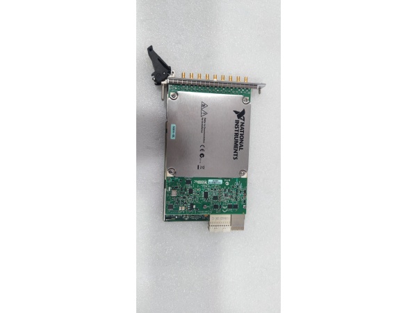
NI PXIe-5105
The Real-World Problem It Solves
Benchtop scopes max out at four channels. Data loggers multiplex inputs, introducing microsecond skew between channels that kills phase coherence. The PXIe-5105 gives you eight true parallel channels in one 3U slot, each with independent front-end conditioning and dedicated ADC. For ultrasonic phased arrays or radar beamforming, that simultaneity isn’t a luxury—it’s the difference between resolving a defect and missing it entirely.
Where you’ll typically find it:
-
Ultrasonic NDT systems: Phased array weld inspection, capturing eight element signals to reconstruct beam steering; 60 MHz bandwidth handles 15 MHz transducers with margin.
-
Radar/sonar signal capture: Multi-channel IF processing in tactical systems; PXI trigger bus synchronizes multiple 5105 modules for 16+ channel arrays.
-
Power electronics test: Simultaneous Vce and Ic capture on three-phase inverters; 12-bit resolution catches switching transients without range switching delays.
Bottom line: It replaces a rack of synchronized scopes with one module, tied to chassis trigger lines, not BNC cobwebs.
Hardware Architecture & Under-the-Hood Logic
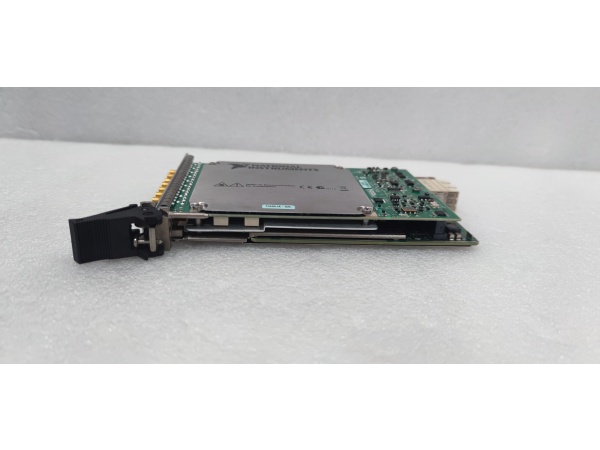
This isn’t a scope with a demux front end. Each channel has its own signal conditioning amp, antialias filter, and 12-bit ADC. All eight ADCs sample off the same 60 MHz clock distribution, ensuring <100 ps channel-to-channel skew. The NI Synchronization and Memory Core (SMC) ASIC handles data packing, triggering, and DMA to host memory without CPU intervention.
-
Input conditioning: Per-channel selectable attenuator (50 mV to 30 V) → AC/DC coupling relay (1 MΩ only) → 24 MHz antialias filter → ADC driver amp.
-
Sampling core: Eight parallel 12-bit ADCs @ 60 MS/s, clocked from common VCXO or external source; samples packed into 256-byte records by SMC.
-
Trigger engine: Digital comparators on each channel for edge, window, hysteresis triggers; PXI backplane triggers routed via SMC crossbar.
-
Memory management: Circular buffer pre-trigger, post-trigger storage in onboard SDRAM; DMA engine streams to host via x4 PCIe Gen1 (200 MB/s sustained).
-
Synchronization: NI-TClk protocol aligns multiple modules; PXI 10 MHz reference or external 1-20 MHz reference phase-locks VCXO for coherent multi-chassis systems.
NI PXIe-5105
Field Service Pitfalls: What Rookies Get Wrong
Confusing 50 Ω and 1 MΩ Input Damage Thresholds
The front panel SMBs look identical, but the protection circuits aren’t. A 50 Ω channel sees a 10V peak input as a near-short and blows the internal termination resistor. A 1 MΩ channel survives 42V peaks but won’t handle the current if you hot-switch a charged coax.
-
Field Rule: Verify range setting in software before connecting. If you smell burning or see DC offset drift on a 50 Ω channel, the termination resistor is toast—send it for calibration/repair. For high-voltage probes, always use 1 MΩ mode and verify probe compensation at 1 kHz square wave.
Ignoring Memory Partitioning Math
512 MB sounds deep until you divide by eight channels and add header overhead. Multirecord mode burns 256 bytes per record minimum—capture 10,000 records and you’ve lost 2.5 MB to headers alone. Rookies set record length to 1M samples, enable all channels, and wonder why they get memory overflow at 50 records.
-
Quick Fix: Calculate before you acquire: Available records = (Memory Option – Header Overhead) / (Record Length × 2 bytes/sample × Channels + 480 bytes). For deep single captures, disable unused channels—they still consume memory when enabled. Use Record mode for single long captures, Multirecord for pulse trains.
Trigger Skew in Multi-Module Systems
Two PXIe-5105 modules in one chassis, both triggering off PXI_Trig0, but the captured waveforms show 10 ns offset. The T-Clock synchronization wasn’t initialized, or the 10 MHz reference isn’t locked.
-
Field Rule: Run NI-TClk Configure and Align routines in software before acquisition—this calibrates trigger path delays between modules. Verify PXI 10 MHz is present (green LED on chassis). For sub-nanosecond skew, use PXI Star trigger (dedicated star line to slot 2) rather than multidrop PXI_Trig lines. Check that both modules report “PLL Locked” status before arming.


