
Description
Hard-Numbers: Technical Specifications
General Specifications
- Resolution: 6½ digits (10 to 23 bits)
- Basic DC Voltage Accuracy (10 V range, 2-year): 25 ppm of reading + 0.5 ppm of range (±0.0025%)
- Warm-up Time: 60 minutes to rated accuracy
- Calibration Interval: 2 years (recommended)
- Measurement Categories: CAT II (up to 300 VDC or Vrms), CAT I (up to 300 VDC, 300 Vrms)
- Environmental: Operating 0°C to 55°C, Storage -40°C to 71°C, Humidity 5% to 95% RH noncondensing
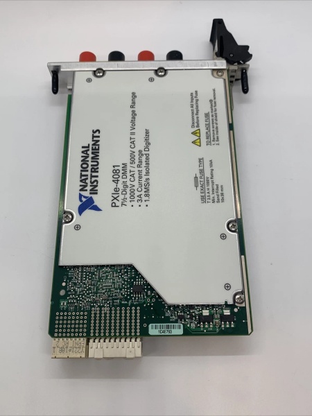
- Physical: 3U single-slot PXIe module, 2.0 cm × 13.0 cm × 21.6 cm (0.8″ × 5.1″ × 8.5″), Weight 340 g (12 oz)
- Power Consumption: <9 W from PXIe backplane (+12 V 0.55 A max, +3.3 V 0.55 A max)
DC Voltage Measurement
- Range: ±100 mV, ±1 V, ±10 V, ±100 V, ±300 V
- Input Resistance: >10 GΩ / 10 MΩ switchable
- Sensitivity: 100 nV
- 24-Hour Accuracy (Tselfcal ±1°C):
- 100 mV range: 10 ppm reading + 4 ppm range
- 1 V range: 6 ppm reading + 2 ppm range
- 10 V range: 6 ppm reading + 2 ppm range
- 100 V range: 6 ppm reading + 3 ppm range
- 300 V range: 6 ppm reading + 3 ppm range
- 90-Day Accuracy (Tselfcal ±5°C): Add +20 ppm of reading + +5 ppm of range
- 2-Year Accuracy (Tselfcal ±5°C): Add +20 ppm of reading + +5 ppm of range
AC Voltage Measurement
- Range (rms): 50 mV, 500 mV, 5 V, 50 V, 300 V
- Frequency Range: 10 Hz to 300 kHz
- Peak Voltage: 425 V (300 Vrms range)
- Accuracy (2-Year, Tselfcal ±10°C):
- 10 Hz to 40 Hz: 0.5% reading + 0.15% range
- 40 Hz to 20 kHz: 0.3% reading + 0.05% range
- 20 kHz to 50 kHz: 0.5% reading + 0.05% range
- 50 kHz to 100 kHz: 1% reading + 0.05% range
- 100 kHz to 300 kHz: 2% reading + 0.2% range
DC Current Measurement
- Range: ±100 µA, ±1 mA, ±10 mA, ±100 mA, ±1 A
- Sensitivity: 10 nA
- 24-Hour Accuracy (Tselfcal ±1°C):
- 100 µA to 10 mA ranges: 40 ppm reading + 6 ppm range
- 100 mA range: 50 ppm reading + 7 ppm range
- 1 A range: 60 ppm reading + 10 ppm range
AC Current Measurement
- Range (rms): 100 µA, 1 mA, 10 mA, 100 mA, 1 A
- Peak Current: 2 A (1 A range)
- Frequency Range: 10 Hz to 10 kHz
- Accuracy (2-Year, Tselfcal ±10°C): Same as DC current + add 50 ppm reading
Resistance Measurement
- Range: 100 Ω, 1 kΩ, 10 kΩ, 100 kΩ, 1 MΩ, 10 MΩ, 100 MΩ
- Sensitivity: 100 µΩ (100 Ω range)
- Maximum Measurement: 100 MΩ
- Modes: 2-wire and 4-wire
- 24-Hour Accuracy (Tselfcal ±1°C):
- 100 Ω to 1 kΩ: 50 ppm reading + 5 ppm range
- 10 kΩ to 100 MΩ: 60 ppm reading + 5 ppm range
Capacitance Measurement (LCR Mode)
- Range: 300 pF, 1 nF, 10 nF, 100 nF, 1 µF, 10 µF, 100 µF, 1000 µF, 10,000 µF
- Accuracy (2-Year, Tselfcal ±10°C):
- 300 pF: 0.5% reading + 0.6% range
- 1 nF to 100 nF: 0.4% reading + 0.2% range
- 1 µF to 10,000 µF: 0.3% reading + 0.1% range
- Effective Test Frequency:
- 300 pF to 100 nF: 3 kHz (Parallel model)
- 1 µF to 10 µF: 1 kHz (Series model)
- 100 µF to 10,000 µF: 91 Hz (Series model)
- DC Bias: 0.46 V from HI to LO, nominal, user-selectable (OFF by default)
- Test Signal Current: 160 nA to 1 mA (depending on range)
- Maximum Reading Rate: 3 S/s to 15 S/s (depending on range)
Inductance Measurement (LCR Mode)
- Range: 10 µH, 100 µH, 1 mH, 10 mH, 100 mH, 1 H, 5 H
- Accuracy (2-Year, Tselfcal ±10°C): 0.5% reading + 0.1% to 1% range (depending on range)
- Effective Test Frequency:
- 10 µH to 100 µH: 30 kHz (Series model)
- 1 mH: 3 kHz (Series model)
- 10 mH to 5 H: 273 Hz (Series model)
- Test Signal Current: 330 nA to 1 mA (depending on range)
- Maximum Reading Rate: 3 S/s to 20 S/s (depending on range)
Frequency/Period Measurement
- Frequency Range: 15 Hz to 500 kHz
- Period Range: 2 µs to 66.67 ms
- Aperture Time: 150 ms
Digitizer Mode (Isolated High-Voltage Digitizer)
- Voltage Ranges: ±100 mV to ±300 V (DC or AC coupled)
- Current Ranges: ±20 mA to ±1 A
- Sample Rate Range: 10 S/s to 1.8 MS/s (r = 1.8 MS/s / y, where y = 1, 2, 3, … 1.8×10⁵)
- Analog Bandwidth: 300 kHz (voltage)
- Resolution: 10-bit to 23-bit (variable with sample rate)
- Coupling: DC or AC selectable
- Maximum Input: 300 VDC or Vrms (CAT II), 300 Vpk
Diode Test
- Range: 10 V
- Test Current: 1 µA, 10 µA, 100 µA, 1 mA
- Accuracy: Add 20 ppm of reading to 10 VDC voltage specifications
NI PXIE-4081 783130-01
The Real-World Problem It Solves
Traditional 6½-digit DMMs measure voltage, current, and resistance but cannot characterize passive components (capacitors, inductors) without a separate LCR meter, increasing equipment cost and rack space. The PXIe-4082 combines a 6½-digit DMM with built-in LCR measurement capability (0.05 pF to 10,000 µF, 1 nH to 5 H) and a 1.8 MS/s isolated digitizer, replacing three instruments in one PXI slot. This eliminates the need for separate DMMs, LCR meters, and digitizers in ATE systems, reducing test time and equipment footprint.
Where you’ll typically find it:
- Power supply validation: Measuring output voltage/current ripple with the digitizer while characterizing output capacitors with LCR mode in one test sequence
- Automotive ECU testing: Verifying sensor inputs with 6½-digit accuracy while testing inductor values in filter networks
- Consumer electronics production: Testing power adapter voltage regulation and simultaneously verifying capacitor/inductor component values in a single station
Bottom line: This DMM replaces three instruments (precision DMM + LCR meter + high-voltage digitizer) in one PXI slot, delivering 23-bit accuracy with 10,000 µF capacitance and 5 H inductance measurement capability, reducing test system cost and footprint.
Hardware Architecture & Under-the-Hood Logic
The PXIe-4082 is built on NI’s FlexADC architecture, which combines a commercial off-the-shelf high-speed ADC with a custom sigma-delta converter to achieve both 6½-digit precision and 1.8 MS/s digitization. The LCR measurement function uses an AC current source as excitation, generating a harmonically limited square wave test signal with fundamental and third harmonic frequencies ranging from 91 Hz to 30 kHz. The measurement method extracts multiple-tone information from the test signal to calculate capacitance and inductance using series or parallel equivalent circuit models, selected automatically based on impedance magnitude. For capacitors >100 µF and <10 nF, parallel models are preferred; for capacitors between 10 nF and 100 µF, series or parallel models apply based on impedance. The same principle applies to inductors, with series models for <1 mH and >1 H inductors, and series/parallel options for 1 mH to 1 H range. The digitizer mode uses the same FlexADC core, providing isolated high-voltage waveform acquisition up to 300 V with DC/AC coupling selection.
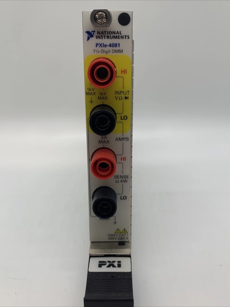
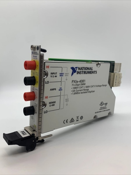
- Signal Input → Front-panel banana connectors receive voltage/current/resistance/capacitance/inductance signals → Input protection circuitry and solid-state range switches route signal to appropriate measurement path
- FlexADC Core → High-speed commercial ADC provides raw digitization → Custom sigma-delta converter applies oversampling and digital filtering → DSP computes DC/AC measurements or extracts LCR parameters → Resolution varies from 10-bit (1.8 MS/s) to 23-bit (6½-digit DMM mode)
- LCR Measurement Mode: AC current source generates test signal → Fundamental and third harmonic frequencies excite DUT → Multiple-tone extraction algorithm calculates capacitance/inductance → Series or parallel model selected based on impedance magnitude → DC bias option (0.46 V) for electrolytic capacitor testing
- DMM Mode (DC/AC voltage/current, resistance, frequency/period) → Uses aperture times ≥100 ms for full accuracy → Auto Zero and ADC calibration enabled for warranted specifications
- Digitizer Mode (isolated, high-voltage) → Samples continuously at 1.8 MS/s with DC/AC coupling selection → Captures waveforms up to 300 Vpk → Isolated front-end protects chassis and controller from high-voltage signals
- Self-Calibration Loop → Precision internal voltage reference → Compares against internal reference to correct DC gain and offset drift → Maintains accuracy across 0-55°C operating range
- Bus Interface → PXI Express Gen 1 x1 lane (250 MB/s) → Transfers measurement data to host controller → Controlled via NI-DMM driver software
- Power Distribution → PXIe backplane provides +12 V and +3.3 V rails → Isolated digitizer section uses dedicated power path → Total power consumption <9 W
NI PXIE-4081 783130-01
Field Service Pitfalls: What Rookies Get Wrong
Forgetting Lead Compensation in LCR Measurements
Technicians measure small capacitors (<10 nF) or small inductors (<1 mH) without performing lead compensation, introducing cable capacitance and inductance errors that corrupt measurements. At 3 kHz test frequency, a 1-meter coaxial cable can add 100-200 pF capacitance, exceeding the accuracy budget for 300 pF to 10 nF measurements.
Field Rule: Always perform lead compensation before LCR measurements. Connect test leads, perform open-circuit compensation (measures cable capacitance/inductance), then short-circuit compensation (measures lead resistance). The PXIe-4082 automatically stores these values and subtracts them from subsequent measurements. Remember: lead compensation must be done after changing cables, cable length, or test frequency. For highest accuracy on small capacitors (<1 nF), use <3 meters of coaxial or shielded twisted-pair cabling.
Misunderstanding Series vs. Parallel LCR Models
Engineers assume the LCR meter always measures capacitance in parallel model, ignoring that the PXIe-4082 automatically selects series or parallel models based on impedance magnitude. For large capacitors (>100 µF) with low impedance, series models provide better results; for small capacitors (<10 nF) with high impedance, parallel models are preferred. Using the wrong model introduces measurement error, especially for electrolytic capacitors with high ESR.
Quick Fix: Verify the default model setting for your measurement range. The PXIe-4082 defaults to parallel model for <10 nF capacitors (impedance >10 kΩ) and series model for >100 µF capacitors (impedance <10 Ω). If your application requires a specific model (e.g., electrolytic capacitor testing with parallel model for ESR measurement), override the default. Remember: model selection affects the measured capacitance/inductance value and associated resistance (ESR for capacitors, DCR for inductors).
Exceeding Digitizer Bandwidth Expectations
Users capture waveforms in digitizer mode assuming the 1.8 MS/s sample rate allows accurate measurement of high-frequency signals. However, the analog bandwidth is only 300 kHz—signals above this frequency are attenuated at -3 dB or more, causing amplitude errors regardless of sample rate.
Field Rule: Treat the PXIe-4082 digitizer as a 300 kHz bandwidth instrument. The 1.8 MS/s sample rate provides oversampling (6× at 300 kHz) for improved resolution and reduced aliasing, but doesn’t extend the analog bandwidth. For signals above 300 kHz, use a dedicated PXIe digitizer with higher bandwidth. If you’re measuring switching power supply ripple with harmonics above 300 kHz, filter the input or use a higher-bandwidth digitizer.
Ignoring LCR Measurement Speed vs. Accuracy Tradeoff
Technicians set maximum reading rate (15-20 S/s) for LCR measurements without considering that higher speed reduces accuracy due to reduced aperture time. For capacitance measurements at 3 kHz test frequency, maximum reading rate is 15 S/s; for 10,000 µF capacitance at 91 Hz, maximum reading rate drops to 3 S/s.
Field Rule: Match reading rate to measurement requirements. For production testing with moderate accuracy requirements (0.5% to 1%), use maximum reading rate to maximize throughput. For metrology-grade accuracy (0.1% or better), reduce reading rate to allow longer aperture time. Remember: LCR measurement accuracy is specified at specific reading rates—exceeding these rates degrades accuracy outside warranted specifications. For critical component characterization, use the lowest reading rate that meets your throughput requirements.
Neglecting Warm-Up Time for LCR Accuracy
Rookies power up the PXIe-4082 and immediately start LCR measurements, ignoring the 60-minute warm-up requirement. The internal reference temperature hasn’t stabilized, causing capacitance/inductance measurements to drift outside the 0.3% to 0.5% accuracy specification.
Field Rule: Power on the PXIe-4082 at least 60 minutes before critical LCR measurements. Monitor the internal temperature via NI MAX—when it stabilizes within ±1°C of ambient, the module is ready. For repeatable metrology work, maintain the chassis at constant temperature and use the self-calibration feature before critical measurements. Remember: warm-up is required every time the module is powered down or ambient temperature changes >5°C.
Commercial Availability & Pricing Note
Please note: The listed price is for reference only and is not binding. Final pricing and terms are subject to negotiation based on current market conditions and availability.


