
Description
Hard-Numbers: Technical Specifications
- Channel Configuration: 64 independent channels arranged in 8 banks of 8 channels each
- Maximum Drive Voltage (External Power): 50 VDC per channel
- Maximum Drive Current: 600 mA per channel, 25 A per module total
- Internal Drive Power: 5 V at 1.25 A, 12 V at 0.5 A (from PXI backplane)
- Single-Channel Operate Time: 60 μs typical (at 25°C)
- Channel-to-Ground Resistance (RDSon): 0.280 Ω maximum (0–600 mA drive current)
- Channel Off Drain Current: 50 μA typical at 13 V, 200 μA typical at 25 V
- Protection Circuitry (Per Channel):
- Overvoltage protection: activates at 80 V maximum
- Overcurrent protection: activates at 1.5 A minimum
- Over-temperature protection: activates at 150°C junction temperature
- Trigger Characteristics:
- Input trigger sources: PXI trigger lines 0–7, Front panel
- Minimum input pulse width: 150 ns (disabling digital filtering allows <150 ns)
- Front panel input voltage: -0.5 V to +5.5 V (+3.3 V nominal TTL)
- Output trigger destinations: PXI trigger lines 0–7, Front panel
- Output trigger pulse width: Programmable 1 μs to 62 μs
- Front panel output: 3.3 V TTL, 8 mA nominal
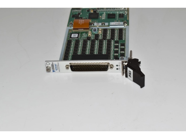
- I/O Connector: 78-pin D-SUB (male)
- PXI Power Requirement: 8 W at 5 V, 0.5 W at 3.3 V, 6 W at 12 V (including optional internal drive power)
- Dimensions: 3U, one-slot PXI/cPCI module, 21.6 × 2.0 × 13.0 cm (8.5 × 0.8 × 5.1 in.)
- Weight: 220 g (8 oz)
- Operating Temperature: 0°C to +55°C
- Storage Temperature: -20°C to +70°C
- Relative Humidity: 5% to 85%, noncondensing
- Maximum Altitude: 2,000 m (indoor use only)
- Shock and Vibration:
- Operational shock: 30 g peak, half-sine, 11 ms pulse
- Random vibration (operating): 5 to 500 Hz, 0.3 grms
- Random vibration (nonoperating): 5 to 500 Hz, 2.4 grms
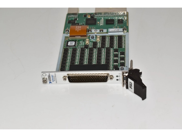
NI PXI-2567
The Real-World Problem It Solves
Most PXI switch modules (like PXI-2564, PXI-2529) have built-in relays with limited drive current—typically 1–2 A max. When your test requires switching higher-power loads or controlling external industrial relays that need 5 A or more coil drive, these standard modules can’t handle it. The PXI-2567 solves this by acting as a relay driver amplifier: it takes low-current PXI control signals and amplifies them to drive up to 600 mA at 50 V per channel, letting you control beefy external relays, solenoids, or motors that would burn out standard switch modules.
Where you’ll typically find it:
- Automotive ECU Functional Test: Driving external power relays that switch ignition coils, fuel injectors, or high-current loads during in-vehicle simulator testing
- Power Supply Validation: Controlling multiple external load banks or high-power contactors via PXI software while maintaining isolation between measurement and power circuits
- Industrial PLC Integration: Bridging PXI test systems to factory floor equipment where existing relays or contactors require higher drive currents than PXI modules can provide
Bottom line: When your test system needs to switch big loads beyond what a standard PXI switch module can handle, the PXI-2567 is your interface between PXI control logic and external power relays. Without it, you’re stuck building discrete driver circuits or risking damage to your PXI equipment by overloading its built-in relays.
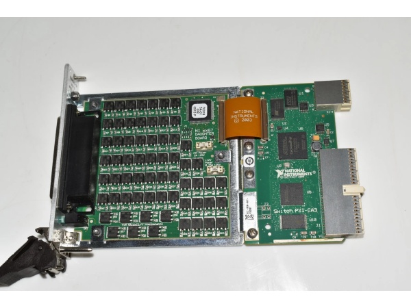
Hardware Architecture & Under-the-Hood Logic
The PXI-2567 is a 3U PXI module containing 64 independent relay driver channels organized in 8 banks of 8 channels. Unlike standard switch modules (PXI-2564, PXI-2529) that integrate physical relays, the PXI-2567 contains driver transistors (FETs or bipolar transistors) that sink current from external relay coils. Each channel includes protection circuitry (overvoltage, overcurrent, overtemperature) and can be powered from either the internal PXI backplane supplies (5 V/12 V) or an external power source for higher drive voltages up to 50 V.
- Host software sends command via PXI bus to NI-SWITCH driver specifying which channel to activate (e.g., “niSwitch_Connect(channel1=’ch0′)”)
- Driver translates to hardware address—maps software channel number to physical bank/channel on module (e.g., Bank 0, Channel 0)
- Module’s FPGA/CPLD decodes command and activates the corresponding driver transistor for that channel—transistor turns ON, sinking current from external relay coil
- External relay coil energizes—current flows from external power supply through relay coil, into PXI-2567 driver channel, to ground (COM return)
- Relay contact closure occurs on external relay—power load switches ON (e.g., motor starts, high-current circuit closes)
- Protection circuitry monitors continuously—overvoltage clamps transients above 80 V, overcurrent cutoff at 1.5 A per channel, thermal shutdown at 150°C junction
- Flyback protection engages when driver turns OFF—internal diode clamps inductive kickback from relay coil to protect driver transistor (critical for relay coil loads)
- Trigger I/O synchronization: If PXI trigger line receives pulse, module can execute pre-configured channel state changes without host processor intervention—enables high-speed relay control (up to 150 ops/sec)
- Power sourcing: Module can use internal PXI backplane power (5 V at 1.25 A, 12 V at 0.5 A) for lower-voltage relays, or external power supply (up to 50 V) for higher-coil-voltage relays—user selects via front panel connector pins (+5 V, +12 V, or external drive voltage)
- Status feedback: Front panel LEDs indicate +5 V and +12 V fuse status—ON = fuse good, OFF = fuse blown (user-replaceable fuses protect internal supplies)
NI PXI-2567
Field Service Pitfalls: What Rookies Get Wrong
Confusing Relay Driver with Relay Module
Techs think the PXI-2567 is a switch module like PXI-2564 or PXI-2529 that has built-in relays. It doesn’t. The PXI-2567 is a driver—it provides transistors to control external relays you wire to it. Rookies try to connect loads directly to the PXI-2567 expecting it to switch power, then wonder why nothing happens or why channels overheat. The module only sinks current from relay coils—it doesn’t have physical contacts for load switching.
Field Rule: Always wire external relays between your power supply and the PXI-2567. Relay coil positive lead goes to power supply (+), coil negative lead goes to PXI-2567 channel pin. The module’s COM pins (CHx:x) provide ground return paths for each bank. Never connect high-voltage power loads directly to PXI-2567 channel pins—this module is for coil drive only, not load switching.
Overloading Internal 5 V/12 V Supplies
Techs try to drive high-current external relays using the internal PXI backplane power (+5 V at 1.25 A, +12 V at 0.5 A). These supplies are limited—drive too many relay coils simultaneously and the internal fuses blow, or the module resets from undervoltage. The front panel LEDs show fuse status, but rookies ignore them until the module 终止s working entirely.
Quick Fix: Calculate total coil current for all relays that will be energized simultaneously. If it exceeds 1.25 A at 5 V or 0.5 A at 12 V, use an external power supply instead. The module supports external drive voltages up to 50 VDC with 600 mA per channel—connect your external supply to the appropriate pins on the 78-pin D-SUB connector and reference the pinout diagram. If you blow an internal fuse, replace it with Littelfuse NANO2 series (2 A at 125 V for +5 V, 0.75 A at 125 V for +12 V).
Ignoring Flyback Diodes for Inductive Loads
Rookies connect relay coils directly to the PXI-2567 without flyback protection. When the driver turns OFF, inductive kickback from the coil can generate voltage spikes exceeding 80 V, triggering overvoltage protection or damaging the driver transistors. While the PXI-2567 has some built-in protection, repeated transients degrade lifespan and cause premature channel failure.
Field Rule: Add a flyback diode across each external relay coil—cathode to coil positive, anode to coil negative. This provides a current path for inductive energy when the driver turns OFF, clamping the voltage spike. For 24 VDC relays, use 1N4007 (1000 V, 1 A) or similar. For 48 VDC relays, use UF4007 or higher-rated diodes. If using AC coils, add RC snubber networks instead. The PXI-2567’s internal protection is a safety net, not a replacement for proper external snubbing.
Mixing Channel Banks Incorrectly
The 64 channels are organized in 8 banks of 8 channels, each with its own common ground return (COM CHx:x). Rookies wire all relays to a single ground return or mix up bank assignments, causing ground loops, shared return paths, or overcurrent on a single COM pin. Each bank has independent ground returns for isolation—wire them wrong and you get noise, crosstalk, or channels not switching.
Quick Fix: Reference the pinout diagram carefully—there are 8 common ground returns (COM CH0:7, COM CH8:15, etc.). Connect relay coils to the correct bank and its associated COM pin. For example, channels 0–7 use COM CH0:7, channels 8–15 use COM CH8:15, etc. Don’t daisy-chain grounds between banks unless you specifically want to share return paths (this reduces isolation). For best noise immunity, keep banks isolated and use twisted-pair wiring for each relay coil and its COM return.
Forgetting to Disable Digital Filtering for High-Speed Triggers
The PXI-2567’s default minimum trigger pulse width is 150 ns due to digital filtering. Rookies trying to trigger at >10 MHz or with ultra-fast timing (<150 ns pulses) wonder why the module ignores trigger signals. The filtering prevents false triggering but limits speed—high-speed test setups need to disable it.
Field Rule: If your application requires trigger pulse widths <150 ns, disable digital filtering in the NI-SWITCH driver configuration. Refer to the NI Switches Help for the specific attribute/property to set (typically
niSwitch_SetAttribute with NISWITCH_ATTR_DIGITAL_FILTER_ENABLED = FALSE). Disabling filtering makes the module more sensitive to noise—only do this if your trigger signals are clean and you need the speed. For most applications (<1 MHz triggers), leave filtering enabled for reliability.Underestimating Power Dissipation at High Drive Currents
Driving 600 mA per channel with 32 channels energized simultaneously means the module dissipates significant heat (P = I²R × N channels). Rookies run high-density tests without checking module temperature, leading to over-temperature protection shutdowns or reduced lifespan from thermal stress. The 150°C junction temperature protection prevents catastrophic failure, but chronic overheating degrades the module.
Quick Fix: Calculate total power dissipation for your worst-case scenario. At 600 mA per channel with 0.280 Ω RDSon, each channel dissipates ~0.1 W (0.6² × 0.28). With 32 channels ON, that’s 3.2 W just in the driver transistors—plus overhead. Ensure your PXI chassis has adequate cooling (fan airflow, empty slots for heat dissipation). If running extended high-current tests, derate per-channel current or add external cooling (chassis fans, ambient temperature control). Monitor module temperature if possible—NI doesn’t expose a temperature sensor, but watch for unexpected resets or channel shutdowns during high-load operation.
Commercial Availability & Pricing Note
Please note: The listed price is for reference only and is not binding. Final pricing and terms are subject to negotiation based on current market conditions and availability.


