
Description
Hard-Numbers: Technical Specifications
-
Valve Type: Two-stage electrohydraulic servo valve (jet pipe first stage, spool second stage)
-
Pilot Stage Technology: Jet pipe (not flapper-nozzle)
-
Flow Rating: ~5.7 L/min (1.5 GPM) at ΔP = 70 bar (1000 psi)
-
Supply Pressure: Max 210 bar (3000 psi) continuous; 315 bar (4500 psi) intermittent
-
Return Pressure: Max 35 bar (500 psi)
-
Frequency Response: ≥60 Hz at –90° phase lag (±10% input, 100% amplitude)
-
Hysteresis: <1% of rated flow
-
Null Shift (Thermal): <0.5% of rated flow (temperature-induced drift)
-
Input Signal: ±10 VDC analog or ±20 mA current command
-
Electrical Connection: MS3106A-10SL-4S (4-pin military circular connector)
-
Operating Temperature: –29°C to +121°C (–20°F to +250°F)
-
Fluid Compatibility: Mineral oil-based hydraulic fluids (ISO VG 32-68), NAS 8-9 cleanliness level minimum
-
Mounting Pattern: ISO 4401-03 or similar (NG6/CETOP 3)
-
Internal Leakage: <0.5% of rated flow at 210 bar
-
Threshold (Sensitivity): <0.5% of rated current
-
Weight: ~0.5-1.0 kg (valve only); ~2 kg with coils and connector

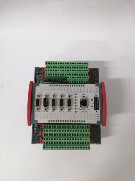
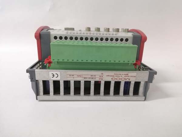
MOOG D136-001-008
The Real-World Problem It Solves
Steam turbine control systems and high-performance hydraulic actuators need precise, fast response to electrical commands without the contamination sensitivity of traditional flapper-nozzle servo valves. The D136-001-008 uses Moog’s jet pipe pilot stage—larger internal clearances than flapper designs—to operate reliably in hydraulic systems with NAS 8-9 cleanliness (common in aging power plants). It converts ±10V or ±20mA command signals into precise hydraulic flow at 60 Hz bandwidth, enabling sub-millisecond response for turbine speed control and flight simulator motion platforms.
Where you’ll typically find it:
-
Steam turbine speed/load control valves in fossil fuel and combined-cycle power plants
-
Six-degree-of-freedom motion platforms for flight/driving simulators
-
Structural testing actuators for fatigue and seismic shake table systems
This valve eliminates the “flapper clogging” failures that plague traditional servo valves in contaminated hydraulic systems while providing the frequency response needed for stable closed-loop control.
Hardware Architecture & Under-the-Hood Logic
The D136-001-008 is not a solenoid valve—it’s a closed-loop electrohydraulic servo valve with two stages of hydraulic amplification and mechanical feedback.
Signal flow and hydraulic logic:
-
Electrical Input: The torque motor (first stage) receives ±10V or ±20mA command. This creates a magnetic field that deflects the jet pipe (a small tube that directs hydraulic fluid).
-
Jet Pipe Amplification: The jet pipe directs high-pressure pilot fluid (typically 70-210 bar) onto two receiver ports. A small mechanical deflection creates a large pressure differential—hydraulic gain #1.
-
Second Stage Spool: The pressure differential acts on the ends of the main spool, causing it to shift. The spool meters flow between pressure (P), tank (T), and ports A/B to the actuator.
-
Mechanical Feedback: As the spool moves, a feedback spring (or wire) pulls the jet pipe back toward center. When spool displacement matches command signal, the system reaches equilibrium—null. This mechanical feedback makes the valve a closed-loop device independent of electronics.
-
Flow Control: Spool land geometry meters flow proportionally to command signal. At 100% command, the spool fully opens to deliver 5.7 L/min at 70 bar ΔP.
-
Contamination Tolerance: The jet pipe has ~10× larger clearances than flapper-nozzle designs. Particles up to 25µm pass through without jamming, compared to 5µm for flapper valves.

MOOG D136-001-008
Field Service Pitfalls: What Rookies Get Wrong
Assuming It’s a Proportional Valve
The D136-001-008 is a servo valve, not a proportional valve. It has <1% hysteresis and 60 Hz response—proportional valves have 5-10% hysteresis and 10-20 Hz response. Swapping a failed servo valve with a proportional valve “that fits the same mounting pattern” destroys closed-loop stability and causes oscillation.
-
Field Rule: Verify the valve type before ordering spares. Check the nameplate for “Servo Valve” and frequency response spec. If the system oscillates at 5-10 Hz after valve replacement, you probably installed a proportional valve. The D136-001-008 requires servo-grade electronics (±10V or ±20mA command, not 0-10V). Check the amplifier gain settings—servo valves need higher gain than proportional valves.
Ignoring Hydraulic Fluid Cleanliness
Jet pipe technology tolerates NAS 8-9, but many techs see “contamination tolerant” and skip filtration maintenance. At NAS 12+, the jet pipe receiver ports erode from particle impingement, causing null shift and gain reduction.
-
Quick Fix: Check fluid cleanliness quarterly with particle counting. Maintain return filtration at β₅ ≥ 200. If the valve exhibits increasing null shift (>2% over a month), the pilot stage is eroding. Replace the valve and upgrade filtration—flushing the system won’t fix eroded receiver ports. Never operate below NAS 9 for extended periods; the “contamination tolerant” claim is relative to flapper valves, not a license for dirty oil.
Mismatched Null Bias
The D136-001-008 has a specific null bias (voltage/current required to center the spool). The D136-001-007 has a different null bias. Swapping them without recalibrating the amplifier causes the actuator to drift when command is zero.
-
Field Rule: Check the null bias spec on the nameplate before installation. If replacing a D136-001-007 with -008, recalibrate the servo amplifier null offset. Drift at zero command indicates wrong null bias. Some amplifiers have a “null trim” potentiometer; adjust this with the command at 0V until actuator stops drifting. If no null trim is available, order the exact suffix match—D136-001-008 is not a drop-in replacement for -007 without recalibration.


