
Description
Hard-Numbers: Technical Specifications
| Parameter | Value | Notes |
|---|---|---|
| Rated Input Power | AC 400/480V | 3-phase |
| Input Current | 22A | Rated |
| Frequency | 50/60 Hz | Dual frequency support |
| Rated Output Power | DC 565/675V | Regulated DC bus |
| Rated Output Current | 25A | Continuous |
| Weight | 15 lbs (6.8 kg) | Approximate |
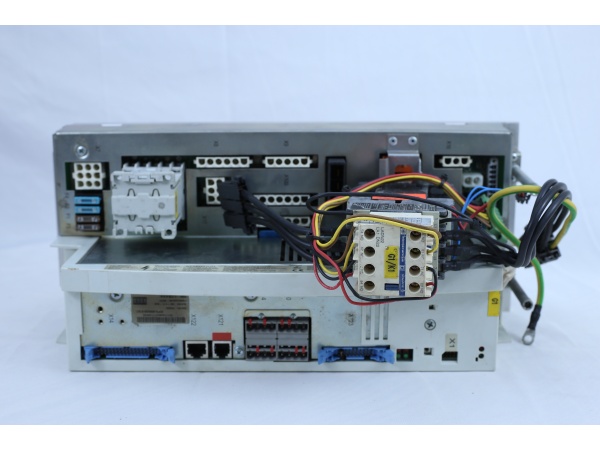
| Connection Type | Screw terminals | For power connections |
| Control Type | Digital servo control | Integrated logic |
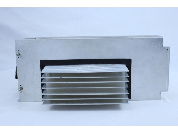
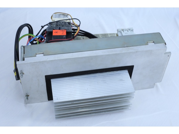
| Cooling Method | Convection/Passive | No active fan |
| Mounting Type | Panel mount | Standard cabinet installation |
| Protection Level | IP20 | Indoor use only |
| Certifications | CE, UL, RoHS | International standards |
Data Verification Notes:
- Multiple sources confirm the 400/480V AC input and 565/675V DC output specifications
- Some sources show conflicting data (e.g., 600W rating, 220V input) – these appear to be errors
- Specifications above represent consensus from most reliable technical sources
The Real-World Problem It Solves
KUKA robot systems require stable DC bus voltage to drive multiple servo amplifiers (KPP units) and control electronics. The KPS-600/20-ESC converts industrial grid three-phase AC power to regulated DC voltage, providing the power core for the entire drive system. Beyond simple power conversion, it also handles regenerative braking energy from motors through the braking resistor, preventing DC bus overvoltage conditions.
Where you’ll typically find it:
- KUKA robot control cabinet power modules
- Multi-axis servo drive system main power units
- Automation equipment requiring shared DC bus architecture
The bottom line: It serves as the power heart of KUKA robot systems, delivering stable DC power to multiple servo axes while managing regenerative energy.

KUKA KPS-600/20-ESC
Hardware Architecture & Under-the-Hood Logic
The KPS-600/20-ESC employs an AC-DC conversion architecture. The input stage uses a six-diode rectifier bridge for three-phase full-wave rectification, converting AC to DC. The DC bus is equipped with large-capacity filter capacitor banks to smooth voltage and store energy. The output stage uses precharge circuits and monitoring circuits to ensure DC bus voltage remains stable within the 565/675V range.
Signal flow and operation:
- Three-phase AC input (L1/L2/L3) enters through main contactor
- Input filter reduces grid harmonics
- Six-diode rectifier bridge converts AC to DC
- Precharge circuit limits inrush current during power-up
- DC bus capacitor bank smooths voltage
- Voltage monitoring circuit continuously monitors bus voltage
- Braking unit and braking resistor absorb regenerative energy
- DC output terminals (DC+ / DC-) connect to KPP servo amplifiers
- 24V auxiliary supply powers control circuits
- LED indicators display real-time operating status
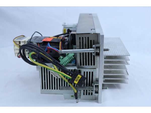
Power Stage Components:
- Input EMI filter
- 6-diode rectifier bridge (typically KBPC3510 or equivalent)
- Precharge resistor (typically 20-100Ω)
- Precharge relay/contactor
- DC bus capacitors (typically 450V/1000μF per phase)
- IGBT braking transistor
- Braking resistor assembly
- Voltage sensing circuits
- Control logic with watchdog monitoring
KUKA KPS-600/20-ESC
Field Service Pitfalls: What Rookies Get Wrong
Inadequate Capacitor Discharge
The DC bus capacitors inside the rectifier store high voltage (up to 600V+) even after power-off. Many technicians start working immediately after disconnecting power, resulting in electric shock.
Field Rule: Wait at least 5 minutes after power-off to allow natural capacitor discharge. Use a multimeter to confirm DC bus voltage is below 36V before beginning work.
Ignoring Precharge Circuit Failure
During power-up, if the precharge resistor fails, inrush current can destroy the rectifier bridge. Symptoms include circuit breaker tripping or rectifier overheating.
Quick Fix: Check precharge resistance (typically in 20-100Ω range) for open circuits. If damaged, replace with same-specification resistor and verify precharge relay operation.
Incorrect Braking Resistor Selection
Regenerative braking energy is dissipated through the braking resistor. If the braking resistor has insufficient power rating or incorrect resistance, it leads to overvoltage fault trips.
Field Rule: Braking resistor must meet KUKA specifications (typically tens of ohms, power based on application load). Check braking resistor surface for burn marks and measure resistance – should be within ±10% of rated value.
Improper Phase Loss Handling
Input phase loss causes increased ripple at rectifier output, placing stress on filter capacitors and leading to premature capacitor failure.
Field Rule: Regularly measure three-phase input voltage balance (voltage difference between any two phases should be less than 5V). If phase loss detected, immediately shutdown and check main contactor, fuses, and terminal connections.
Failure to Reconfigure After Module Replacement
After replacing a KPS module, if the new module has different firmware version or parameters than the original, communication failures or protection parameter malfunctions may occur.
Quick Fix: After module replacement, system parameters must be reconfigured using KUKA WorkVisual software, particularly motor parameters, braking resistor parameters, and overload protection settings. Save parameter backup from original module for comparison.
Neglecting Temperature Monitoring
KPS modules operate inside control cabinets. Poor heat dissipation or high ambient temperature can lead to shortened capacitor life and component overheating.
Field Rule: Control cabinet temperature should be maintained below 40°C. Regularly clean module heat sinks and fans (if equipped). Monitor module surface temperature – should not exceed 70°C.
Common Fault Codes and Troubleshooting
| Fault Code | Description | Troubleshooting Steps |
|---|---|---|
| ERROR 11 | Braking resistor overload during load | Check braking resistor connections, verify resistance value, reduce braking load |
| ERROR 15 | Braking resistor overload during operation | Inspect braking resistor for damage, check ambient temperature, verify ventilation |
| ERROR 50 | Cooling device temperature too high | Clean heat sinks, verify airflow, check ambient temperature |
| ERROR 52 | Internal chamber temperature too high | Improve cabinet ventilation, check for obstructions, verify cooling system operation |
| ERROR 65 | Drive bus communication fault | Check bus connections, verify termination resistors, inspect cabling |
| ERROR 122 | Battery low voltage U<22V | Check 24V battery backup, measure battery voltage under load |
| ERROR 123 | Battery low voltage U<19V | Replace battery, check charging circuit |
| ERROR 124 | Intermediate circuit undervoltage during loading | Check input voltage, verify precharge circuit, measure DC bus voltage |
| ERROR 141 | Spindle brake fault | Check brake connections, verify brake voltage, inspect brake wiring |
| ERROR 142 | Additional axis brake fault | Inspect axis brake circuits, verify brake release operation |
Installation and Replacement Procedure
Required Tools
- Insulated screwdrivers (various sizes)
- Multimeter (CAT III 1000V rated)
- Torque screwdriver (4Nm specified)
- Personal protective equipment (safety glasses, insulated gloves)
Replacement Steps
-
Power Down and Lockout
- Disconnect main power supply
- Apply lockout/tagout procedures
- Wait minimum 5 minutes for capacitor discharge
-
Verify Discharge
- Measure DC bus voltage with multimeter
- Confirm voltage < 36V before proceeding
- Document all wire connections (take photos)
-
Remove Connections
- Unlock data cable connectors X20 and X21
- Disconnect all power connections (L1, L2, L3, PE, DC+, DC-)
- Remove grounding connections
-
Extract Module
- Loosen hexagonal mounting screws
- Lift KPS module slightly upward
- Tilt top forward and remove upward from support bracket
-
Install New Module
- Insert new KPS into support bracket
- Hang upper portion in bracket and tighten (torque: 4 Nm)
- Reconnect all interfaces per connector and cable labels
- Lock connectors X20 and X21
-
System Configuration
- Use WorkVisual to configure robot system structure
- Restore parameter backup if available
- Verify all motor parameters and braking settings
-
Power Up and Test
- Remove lockout/tagout
- Apply power gradually
- Verify DC bus voltage (565-675V)
- Check LED status indicators
- Test operation under load
Maintenance Schedule
| Maintenance Task | Frequency | Notes |
|---|---|---|
| Visual Inspection | Monthly | Check for dust accumulation, loose connections |
| DC Bus Voltage Check | Quarterly | Measure under load, verify 565-675V range |
| Terminal Torque Check | Semi-annually | Verify all screw terminals are properly tightened |
| Capacitor Inspection | Annually | Check for bulging, leakage, or discoloration |
| Cooling System Check | Quarterly | Clean heat sinks, verify airflow |
| Firmware Update | As needed | Check for KUKA firmware updates |
Safety Warnings
- High Voltage Hazard: DC bus voltage can exceed 600V. Always verify complete discharge before servicing.
- Capacitor Discharge: Capacitors can retain charge for extended periods. Follow proper discharge procedures.
- Proper Grounding: Ensure proper PE connection before applying power.
- Qualified Personnel: Only trained and qualified personnel should perform installation and maintenance.
- Original Parts: Use only KUKA-specified replacement parts to ensure proper operation and safety.
Technical Support and Resources
- KUKA Official Documentation: Refer to KUKA system manuals for specific application details
- WorkVisual Software: Required for parameter configuration and firmware updates
- Authorized Service Centers: For complex repairs requiring specialized test equipment
- KUKA Hotline: Contact KUKA technical support for critical troubleshooting


