
Description
Hard-Numbers: Technical Specifications
- CPU Type: PowerPC 8245
- CPU Speed: 400 MHz
- Memory: 32 MB SDRAM, 16 MB Flash
- Power Supply: 24 VDC ±20% (19.2–28.8 VDC)
- Power Consumption: Maximum 20 W
- Digital I/O: 4 general purpose digital inputs, 4 general purpose digital outputs
- Serial Interfaces:
- 12 × RS-232/RS-422/RS-485 (general purpose)
- 4 × Isolated RS-232/RS-422/RS-485
- Network Interfaces:
- 2 × CAN bus (1 Mbps)
- 2 × Profibus (12 Mbps)
- 2 × 100 Mbps Ethernet LAN
- SPBus Interface: 1 × Serial Process Bus for RIO 400 remote I/O (RS-485, up to 2 MHz, 500V isolated)
- Redundancy: Prepared for redundant RCU operation with hot-replacement capability
- Diagnostics: Built-in Self-Test (BIST), watchdog with system status output, high-temperature and cooling fan alarms
- Operating Temperature: 0°C to +70°C
- Storage Temperature: -25°C to +70°C
- Humidity: Up to 98% RH (non-condensing)
- Protection: IP20
- Certifications: IEC 61508, IEC 61131-2, IEC 60945, IACS E10; DNV, ABS, TÜV Rheinland type approval
- Dimensions: 355 mm × 158 mm × 87 mm (14″ × 6.2″ × 3.4″)
- Weight: 1.35 kg
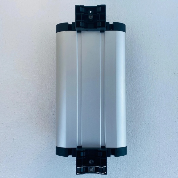
- Mounting: DIN standard rail-mounting with plug-in connections
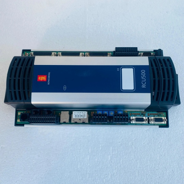
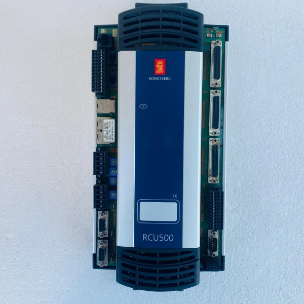
Kongsberg RCU500
The Real-World Problem It Solves
Marine and offshore safety systems can’t afford single points of failure. Dynamic positioning systems, vessel control systems, and fire & gas safety systems require redundant controllers with hot-swap capability to maintain availability in harsh environments. A standard PLC without redundancy creates vulnerability—if the controller fails, the entire system goes offline. The RCU500 provides a PowerPC-based remote controller with comprehensive communication interfaces, built-in diagnostics, and support for redundant configurations with hot-swap capability. When one unit fails, the redundant unit takes over without operator intervention, maintaining continuous system operation.
Where you’ll typically find it:
- Dynamic positioning (DP) systems on offshore platforms and vessels
- Fire and gas safety systems (AIM Safe) with redundant controller architecture
- Vessel control systems requiring SIL 3 compliance
- Process control systems in marine and offshore applications
Bottom line: The RCU500 is the brains of your marine safety system—redundant power, hot-swap capability, and comprehensive diagnostics ensure your system stays online when the going gets rough.
Hardware Architecture & Under-the-Hood Logic
The RCU500 is a remote controller unit based on a PowerPC 8245 single board computer running at 400 MHz. It’s designed as a drop-in replacement for the older SBC400 and SPBUS400 units, combining both functionalities in a single DIN-rail mounted enclosure. The unit communicates with field equipment via SPBus to RIO 400 remote I/O modules and connects to operator stations via dual Ethernet LAN interfaces.
-
PowerPC Processing Platform: The 400 MHz PowerPC 8245 processor provides real-time computing capability for AIM (Alarm & Interlock Management) and DP (Dynamic Positioning) applications. With 32 MB SDRAM and 16 MB Flash memory, the unit runs Kongsberg’s safety-certified software stack. The processor handles logic execution, communication protocols, and diagnostic monitoring simultaneously.
-
Communication Architecture: The RCU5 00 features multiple communication interfaces:
- Dual 100 Mbps Ethernet: Connects to operator stations and upper-level systems. Both ports are active simultaneously for redundancy—if one fails, the other maintains communication.
- Profibus Dual Interface: Provides connection to third-party Profibus devices. Operating at 12 Mbps, this interface supports PROFIdrive and other Profibus profiles.
- Dual CAN Bus: At 1 Mbps, CAN interfaces connect to vehicle control systems or CANopen devices. Both interfaces are isolated and support redundancy.
- SPBus Interface: The Serial Process Bus connects to RIO 400 remote I/O units for distributed I/O. Operating at up to 2 MHz with 500V isolation, SPBus uses RS-485 physical layer with Manchester encoding for noise immunity.
-
Built-in Self-Test (BIST): The unit continuously runs internal diagnostics to detect hardware faults. BIST covers processor health, memory integrity, communication interface status, and power supply monitoring. Faults are reported to operator stations via the communication interfaces. If a critical fault is detected, the unit enters failsafe state and the redundant RCU500 (if configured) takes over.
-
Watchdog and System Status: A hardware watchdog monitors processor activity. If the watchdog timer expires (indicating processor lockup), the unit resets and triggers system status output to alert external monitoring systems. This ensures a hung controller doesn’t silently compromise safety function.
-
Digital I/O Channels: Four general purpose digital inputs and four digital outputs provide local I/O for basic interlocks or status indication. These channels are isolated from the main logic and can be used for safety-related functions when properly configured in the application software.
-
Redundancy and Hot-Swap: The RCU500 supports redundant configurations where two units operate in parallel. If one unit fails, the other maintains system operation. The hot-swap capability allows replacement of a failed unit without shutting down the system—disconnect the failed unit, insert the replacement, and the system synchronizes automatically.
Kongsberg RCU500
Field Service Pitfalls: What Rookies Get Wrong
Mixing Non-Isolated and Isolated Serial Interfaces Incorrectly
The RCU5 00 has both non-isolated and isolated serial interfaces (RS-232/RS-422/RS-485). Rookies wire long-distance serial connections to the non-isolated ports without considering ground potential differences. Ground loops cause erratic communication, data corruption, or port damage. The isolated ports are designed for long-distance or multi-drop applications where ground potentials differ.
- Field Rule: Use isolated serial interfaces (the four designated isolated ports) for long-distance cable runs (>10m), multi-drop RS-485 networks, or connections to equipment with different ground references. Reserve non-isolated ports for short-distance, same-reference connections (e.g., local panel equipment). Verify isolation rating (typically 500V) is sufficient for your application.
Ignoring SPBus Termination and Biasing
The SPBus interface connects to RIO 400 remote I/O units via RS-485. Rookies forget to install termination resistors on the first and last nodes of the SPBus segment. The unterminated bus causes signal reflections, leading to communication errors, sporadic I/O failures, or complete communication loss. Worse, they bias the bus incorrectly or not at all, causing marginal operation that fails in high EMI environments.
- Quick Fix: Install 120Ω termination resistors on the first and last RIO 400 units on the SPBus segment. Verify termination by measuring resistance between the A-line and B-line at the open end—should be ~60Ω (two 120Ω resistors in parallel). Ensure the RCU5 00’s SPBus port is properly configured for termination if it’s the last node.
Overlooking Cooling Fan Failure and High-Temperature Alarms
The RCU5 00 has built-in high-temperature and cooling fan alarms. New engineers ignore these alarms or silence them without investigating. The cooling fan degrades over time—dust buildup, bearing wear, or motor fatigue reduces airflow. Internal temperatures rise above 70°C, causing the unit to derate or fault. If ignored, prolonged overheating damages capacitors and reduces component life.
- Field Rule: During routine maintenance, inspect the cooling fan for smooth rotation, bearing wear, and dust buildup. Clean fan blades and vents with compressed air. Monitor internal temperature via the operator station diagnostics—should be <60°C under normal load. If high-temperature alarm occurs, verify fan operation and cabinet airflow immediately before the unit faults.
Forgetting to Configure Watchdog Output for Redundant Systems
In redundant RCU5 00 configurations, the watchdog output signals that one unit has failed. Rookies fail to wire this output to an external alarm or the redundant unit’s status input. When the primary unit fails, the redundant unit doesn’t get notification to take over, or operators aren’t alerted to the failure. The redundant configuration exists on paper but doesn’t work in practice.
- Quick Fix: Wire the watchdog output (status relay or discrete output) to the redundant RCU5 00’s fault input and to an alarm panel. Verify that when the primary unit fails (simulated by removing power), the redundant unit detects the fault and takes over system control without operator intervention. Document the watchdog wiring in system schematics.
Improper Grounding of SPBus Shield
The SPBus uses shielded twisted-pair cable for noise immunity. Techs ground the shield at both ends—creating ground loops that corrupt RS-485 signals. In marine installations with multiple grounding points, this causes intermittent communication failures that are temperature-dependent or load-dependent—system works during the day but fails at night when equipment shuts down and ground potentials shift.
- Field Rule: Terminate the SPBus shield at the RCU5 00 end only (single-point grounding). Leave the shield floating at the RIO 400 units or connect via a capacitor (1–10 nF) to block DC ground loops. Never ground shields at both ends unless using shielded cable specifically designed for multi-point grounding. Verify shield continuity with a multimeter and check for ground loops by measuring resistance between shield and PE at multiple points—should be >1MΩ except at the grounding point.
Neglecting BIST Fault Log Review
The Built-in Self-Test (BIST) generates fault logs that indicate degrading components before they cause complete failure. New engineers only check for active faults and ignore historical fault logs. Over time, the log shows increasing communication errors, intermittent watchdog resets, or power supply fluctuations—precursors to catastrophic failure. By the time a full fault occurs, the unit fails unexpectedly without warning.
- Field Rule: During quarterly maintenance, export and review the BIST fault log from the operator station. Look for trends—increasing retry counts on SPBus, sporadic watchdog resets, fluctuating power supply voltage. If trends indicate degradation, plan for unit replacement or investigate root cause (cabling, power supply, ambient conditions). Proactive maintenance beats emergency downtime.
Commercial Availability & Pricing Note
Please note: The listed price is for reference only and is not binding. Final pricing and terms are subject to negotiation based on current market conditions and availability.


