
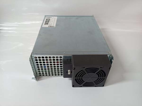
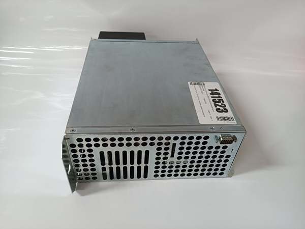
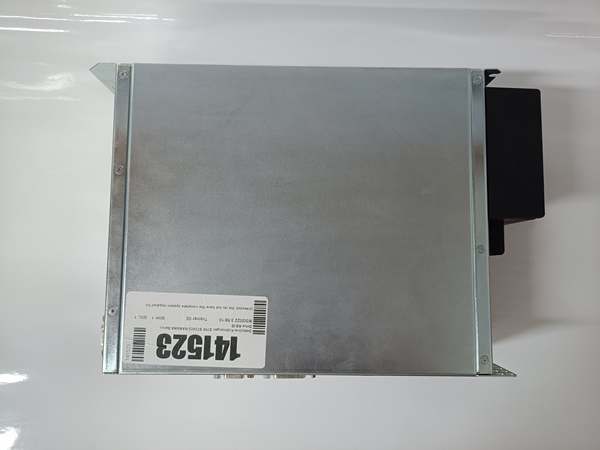
Description
Hard-Numbers: Technical Specifications
- Analog Input Range: ±10V differential
- Input Impedance: 100 kΩ (differential)
- Resolution: 16-bit A/D conversion (approx. 0.3 mV/bit)
- Bandwidth: 500 Hz (-3dB)
- Control Modes Supported: Torque, Velocity, Position (with external feedback)
- Max Output Current: 8.5A continuous (depends on base drive rating)
- Peak Current: 17A for 1 second
- Gain Adjustments: Software-configurable via parameter P-0-xxxx series
- Offset Adjustment: Software-configurable, ±10% of command range
- Isolation Rating: 500V optical isolation (analog to drive logic)
- Power Draw: 2.0W max from S700 backplane
- Operating Temperature: 0°C to +50°C (32°F to +122°F)
- LED Indicators: PWR, ERR, SIG (signal status)

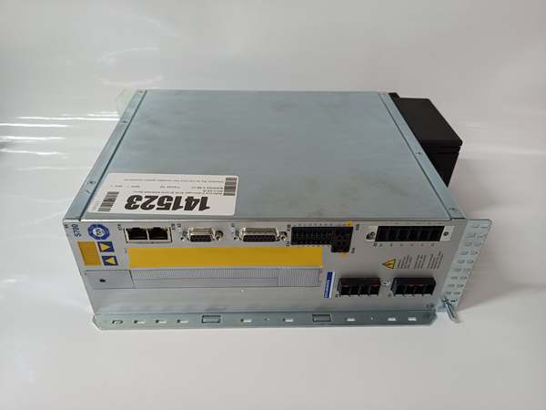
Kollmorgen S72402-NANANA
The Real-World Problem It Solves
You’ve got a perfectly functional PLC control system pumping out ±10V analog signals, and upgrading to a full fieldbus architecture would cost six figures in retrofit and reprogramming. The S72402-NANANA lets your modern S700 drive talk to legacy control systems through a simple analog interface, avoiding a complete control overhaul.
Where you’ll typically find it:
- CNC retrofit projects where the old control system stays in place
- Extruder drives using analog speed reference from process controller
- Tension control applications with load cell feedback through PLC analog output
The bottom line: It bridges old and new technology without requiring a full control system upgrade—perfect when your budget says “analog” but your performance needs say “servo.”
Hardware Architecture & Under-the-Hood Logic
This card is essentially a high-precision analog front-end that converts voltage signals into digital values the S700 main processor understands. The analog path is optically isolated to protect against ground loops and electrical noise, critical in industrial environments.
Signal flow breaks down like this:
- ±10V command signal enters through the differential input connector
- 16-bit ADC samples the analog value and converts to digital word
- Isolation barrier transfers digital data to the drive processor
- Processor applies gain and offset scaling per parameter configuration
- Scaled command becomes torque/velocity setpoint for servo loops
- Error checking monitors for out-of-range and signal loss conditions
- LED status indicates signal validity and fault conditions
Kollmorgen S72402-NANANA
Field Service Pitfalls: What Rookies Get Wrong
Differential vs. Single-Ended WiringTechs connect the analog command single-ended to ground, creating a ground loop when the PLC and drive have different ground references. This causes erratic motion, drift, and mysterious faults that disappear when you disconnect the shield.
- Field Rule: Always wire analog commands differentially. Use the AIN+ and AIN- terminals, never connect AIN- to ground directly. If you must use single-ended, install a signal isolator module between the PLC and drive.
Ignoring Signal Range CalibrationThe ±10V range is nominal, but actual output varies between PLCs. Techs assume 0V = 0 torque and 10V = full torque, then the motor doesn’t reach rated speed or creeps at zero command.
- Quick Fix: Calibrate during commissioning. Apply 0V, 5V, and 10V from the PLC and verify actual speed/torque at each point. Adjust P-0-xxxx gain and offset parameters until 0V yields zero speed and 10V hits rated output. Document these values—they save hours during troubleshooting.
Missing Signal Loss DetectionAnalog wires can break or disconnect, leaving the command floating. Without signal loss detection, the drive holds the last known value and the axis keeps running after the cable breaks—a dangerous situation.
- Field Rule: Enable signal loss detection (Parameter P-0-0134 or similar). Set a detection window (typically ±500mV) and response action (fault or hold). Test it by unplugging the cable during a safe part of the cycle—the drive should fault immediately.


