
Description
Hard-Numbers: Technical Specifications
- Analog Input: ±10V differential, 16-bit resolution
- Analog Output: 0-10V (monitoring/feedback), 12-bit resolution
- Digital Inputs: 8 opto-isolated inputs, 24VDC logic
- Digital Outputs: 4 transistor outputs, 500mA per channel
- Input Response Time: 1ms max (digital), 2ms (analog)
- Isolation Rating: 500V optical isolation (all I/O to drive logic)
- Power Draw: 4.5W max from S700 backplane
- Operating Temperature: 0°C to +50°C (32°F to +122°F)
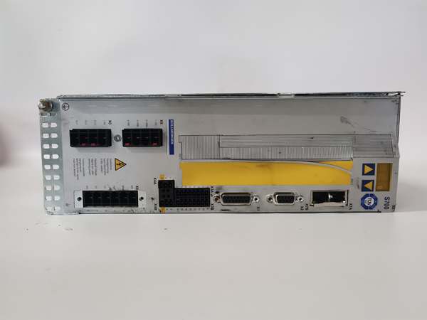
- LED Indicators: PWR, ERR, IN1-4, OUT1-2 (status diagnostics)
- Encoder Support: Optional differential encoder input (A/B/Z lines)
- Max Wire Size: 22-14 AWG (terminal block)
- IP Rating: IP20 (card level), system IP depends on drive enclosure

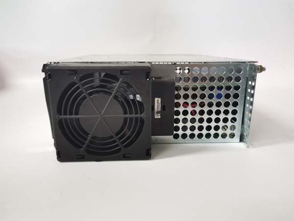
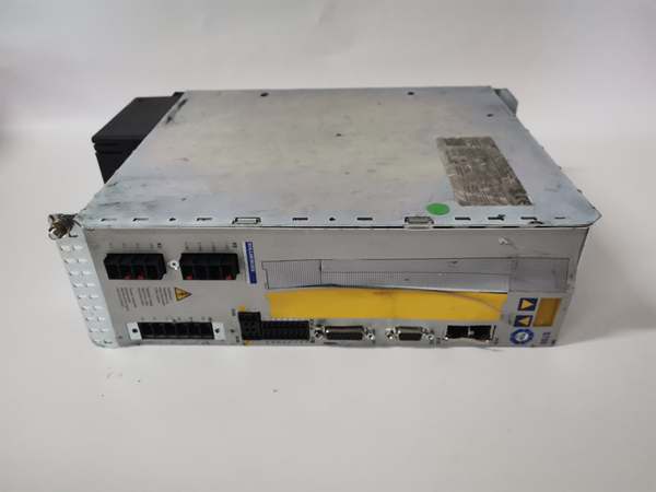
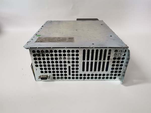
Kollmorgen S72402-NANANA-NA
The Real-World Problem It Solves
You need both analog speed reference and multiple digital signals for limit switches, e-stops, and status indicators, but the base drive only offers a handful of I/O points. This module expands your I/O capacity and provides monitoring outputs without requiring external signal conditioning or additional interface cards.
Where you’ll typically find it:
- Retrofitted machining centers with legacy analog controls but modern safety systems
- Material handling lines requiring speed reference from PLC with multiple zone interlocks
- Tension control applications using analog reference with digital load cell interfacing
The bottom line: It consolidates what would otherwise require multiple interface cards and external wiring into a single module, reducing cabinet space and potential failure points in mixed-signal applications.
Hardware Architecture & Under-the-Hood Logic
This card is essentially a hybrid interface hub that combines A/D conversion, D/A output, and digital signal conditioning on one board. The analog paths feature differential inputs and outputs with optical isolation, while digital channels use optocouplers for noise immunity.
Signal flow breaks down like this:
- ±10V command signal enters through differential analog input
- 16-bit ADC samples and converts to digital value with isolation barrier
- Digital I/O channels route through optocouplers to the drive processor
- Drive processor applies scaling and logic to all signal channels
- Analog monitoring output generates 0-10V feedback from internal variables
- Status information drives front-panel LED indicators for each I/O group
- All I/O exchanges data with main drive processor over backplane bus
Kollmorgen S72402-NANANA-NA
Field Service Pitfalls: What Rookies Get Wrong
Mixing I/O ReferencesTechs wire the analog command 0V to digital input ground, creating ground loops that cause erratic behavior on both systems. The analog and digital sections are isolated separately for a reason.
- Field Rule: Keep analog reference separate from digital common. Use star wiring at the ground point—don’t daisy-chain grounds between different signal types. If you’re seeing cross-talk, isolate the analog side with a signal conditioner.
Overloading Digital OutputsEach transistor output is rated for 500mA, but techs wire multiple relays in parallel or connect high-inductive loads directly. The outputs overheat and fail, taking down the whole card.
- Quick Fix: Calculate load current for each output. If you’re driving more than 400mA, use an external relay or interposing contactor. For inductive loads, add a flyback diode across the coil—reverse-biased, cathode to positive.
Ignoring Analog Output ScalingThe 0-10V monitoring output is great for troubleshooting, but it needs proper scaling. Techs assume 10V equals rated speed, then wonder why their panel meter reads 7.5V at full speed.
- Field Rule: Check the monitoring output scaling parameters (P-0-0250 series). Configure them so 10V corresponds to your actual operating range (rated speed or max application speed). Document this—you’ll thank yourself later when troubleshooting speed discrepancies.


