
Description
Hard-Numbers: Technical Specifications
- Continuous Power Output: 20 kW (27 HP)
- Input Voltage: 380-480VAC, 3-phase, 50/60Hz
- Output Current: 40A continuous, 80A peak
- Output Voltage: 0-500VDC (bus)
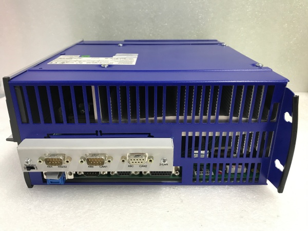
- Control Modes: Torque, Velocity, Position (with external controller)
- Feedback Support: Resolver, EnDat, Hiperface, Analog Encoder
- Switching Frequency: 4/8 kHz selectable
- DC Bus Voltage: 560VDC nominal
- Regenerative Capability: Yes (internal or external resistor option)
- Efficiency: 96% at rated load
- Operating Temperature: 0°C to +50°C (32°F to +122°F)
- Protection Rating: IP20 (indoor cabinet mount), IP65 option available
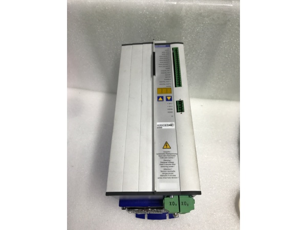
- Dimensions: 250mm × 500mm × 250mm (H×W×D)
- Weight: 45 kg (99 lb)

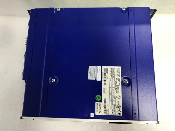
KOLLMORGEN SERVOSTAR TM620 S62000
The Real-World Problem It Solves
You need serious motion power—20kW worth—but most drives that size are either unreliable, impossible to configure, or priced like luxury cars. The TM620 delivers industrial-grade muscle with proven reliability and straightforward parameterization, avoiding the bleeding-edge complexity of newer, less-proven high-power systems.
Where you’ll typically find it:
- Main spindle drives on large CNC machining centers
- Extruder screw drives in plastics processing
- High-speed conveyor and material handling systems
The bottom line: It’s the workhorse of the SERVOSTAR family—20kW of proven servo power that keeps running in harsh environments where exotic drives would choke.
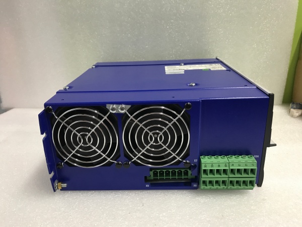
Hardware Architecture & Under-the-Hood Logic
This drive follows the standard high-power servo topology: 3-phase AC input rectified to DC bus, then inverted back to 3-phase AC for the motor. The power stage uses IGBT modules with parallel devices to handle 40A continuous current. Control logic runs on a DSP with dedicated motion coprocessor for real-time servo loops.
Signal flow breaks down like this:
- 3-phase AC enters through L1, L2, L3 input terminals
- Input rectifier converts AC to DC bus (560VDC nominal)
- Precharge circuit limits inrush current during power-up
- DC bus capacitors smooth the rectified DC
- Inverter stage (IGBT bridge) converts DC back to variable-frequency 3-phase AC
- Motor current measured via Hall-effect sensors
- DSP executes current/voltage/position loops at 4-8 kHz
- Feedback device (resolver/encoder) provides position information
- Regenerative circuit dumps excess energy back to line or external resistor
KOLLMORGEN SERVOSTAR TM620 S62000
Field Service Pitfalls: What Rookies Get Wrong
Input Power VerificationTechs assume the nameplate voltage matches the actual supply. Feed this drive 380V when it expects 480V, and it’ll run but derate significantly. Feed it 575V and you’ll blow the input rectifier instantly.
- Field Rule: Measure line-to-line and line-to-neutral voltage at the drive terminals during startup with a True RMS multimeter. Verify it falls within the 380-480V range before applying enable signal. Document this in your startup log.
DC Bus Precharge BypassThe precharge resistor limits inrush current to protect the input rectifier. I’ve seen techs jumper across it to speed up power-up tests, then wonder why the rectifier fails weeks later from the stress.
- Quick Fix: Never bypass precharge. If power-up takes too long (>3 seconds), the precharge circuit is failing—measure resistance across the resistor (should be 20-50Ω). Replace it, don’t defeat it. A $50 resistor saves a $2000 rectifier.
Missing Dynamic Brake ResistorHigh-power drives with rapid deceleration dump massive energy into the DC bus. Without proper regenerative handling, the bus voltage climbs to 700V+ and trips overvoltage protection, or worse, blows the bus capacitors.
- Field Rule: Calculate your deceleration energy (0.5 × J × ω²). If it exceeds the internal braking capacity (check parameter P-0-0040), you need an external resistor. Wire it with proper gauge cable (minimum 10 AWG) and verify thermal rating matches your worst-case 终止 cycle.


