
Description
Hard-Numbers: Technical Specifications
-
Protocol Support: Proprietary CXP backplane bus (to CXP-544A CPU), no direct fieldbus
-
Output Channels: 8-16 analog outputs (configuration dependent on firmware/boot ROM)
-
Output Types: ±10 VDC or 4-20 mA (software configurable per channel)
-
DAC Resolution: 12-bit or 14-bit (revision dependent)
-
Output Isolation: Channel-to-channel and system ground isolation (opto or transformer-based)
-
Update Rate: System-dependent via CXP backplane (typically 100-500 ms scan)
-
Load Drive Capability: 500 Ω minimum (current mode), 10 mA max (voltage mode)
-
Accuracy: ±0.1% FS typical, ±0.25% FS max (at 25°C)
-
Temperature Drift: <50 ppm/°C typical
-
Connector Type: High-density DIN or Hirose-style backplane edge connector (CXP rack specific)
-
Operating Temperature: 0°C to +50°C (ambient, cleanroom environment)
-
Storage Temperature: -20°C to +70°C
-
Power Supply: Derived from CXP-544A backplane (typically +5V, ±15V rails)
-
Power Consumption: 5-10 W typical (dependent on channel loading)
-
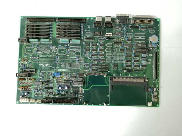
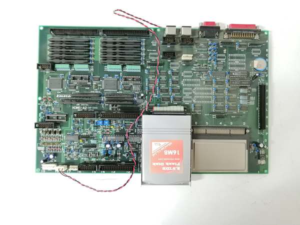
Physical Form: Proprietary PCB with metal EMI shield, edge connector for CXP rack insertion
-
Diagnostic Indicators: Power LED only (no per-channel status indicators)
-
Firmware Dependency: Requires matching boot ROM and CXP-544A system software version
-
Safety/Compliance: SEMI S2/S8 (system level), CE (where applicable)

The Real-World Problem It Solves
Vertical diffusion furnaces running 200mm or legacy 300mm wafers can’t tolerate analog output drift—gas ratios off by 1% mean scrapped wafers and lost batches. The KOMS-A2 eliminates the “analog output uncertainty” headache by providing isolated, configurable DAC channels that drive MFCs and heater power controllers with repeatable precision. It sits between the CXP-544A CPU and the process, translating digital setpoints into the ±10V or 4-20mA signals that control gas flows and zone temperatures in multi-tube vertical furnaces.
Where you’ll typically find it:
-
CVD (Chemical Vapor Deposition) vertical furnaces controlling silane and dopant gas flows
-
High-temperature oxidation/diffusion systems driving multi-zone heater thyristor controllers
-
Annealing furnaces managing hydrogen and nitrogen MFC banks
This board keeps your process recipe execution precise—no channel crosstalk, no ground loop noise, just clean analog control signals in a harsh thermal environment.
Hardware Architecture & Under-the-Hood Logic
The KOMS-A2 isn’t a standalone controller—it’s a slave I/O board in the CXP-544A rack architecture. It communicates over a proprietary parallel backplane bus with the central CPU, receiving digital setpoints and returning channel status. The board contains independent DAC channels with isolation barriers to prevent ground loops between the control system and field devices operating at different potentials in the furnace cabinet.
Internal Signal Flow:
-
Backplane Interface: Receives digital setpoint data from CXP-544A CPU via proprietary high-speed parallel bus
-
DAC Conversion: Each channel’s dedicated DAC converts digital codes to analog voltage or current (±10V or 4-20mA range)
-
Output Buffering: Operational amplifiers buffer the DAC outputs to drive 500Ω loads (current) or capacitive loads (voltage)
-
Channel Isolation: Optocouplers or transformers isolate each channel from system ground and from each other to prevent crosstalk
-
Output Protection: Current limiting and clamping circuits protect against field-side shorts or overvoltage
-
Status Feedback: Limited diagnostic data (channel fault, overrange) sent back to CPU via backplane; no per-channel LEDs visible to operator
KOKUSAI CXP-544A
Field Service Pitfalls: What Rookies Get Wrong
Assuming All KOMS-A2 Boards Are Interchangeable
The KOMS-A2 has firmware revisions tied to specific CXP-544A boot ROM versions and system software. Engineers grab a spare from stores, install it, and watch the furnace fault on “Analog Board Mismatch” or see erratic gas flows because the DAC calibration tables don’t match the CPU’s expectations.
-
Field Rule: Verify the firmware revision sticker on the KOMS-A2 matches the CXP-544A system software version before installation. Check the “System Configuration” printout from the last good startup—note the KOMS-A2 revision letter and serial number. If you must use a different revision, you may need to reload the system software or update the boot ROM. Never hot-swap; the CXP-544A must be powered down for KOMS-A2 replacement due to backplane connector sequencing.
Ignoring the 15-25 Year Capacitor Degradation Timeline
These boards have been in service since the 1990s-2000s. The electrolytic capacitors on the power rails dry out, causing ripple that shows up as noise on the analog outputs. Rookies calibrate the MFCs repeatedly and blame the mass flow controllers when it’s actually the DAC power supply sagging under load.
-
Quick Fix: If you’re seeing >0.5% output drift or intermittent “Analog Board Fault” alarms on a KOMS-A2 older than 15 years, pull the board and check the electrolytics with an ESR meter. Replace any capacitor showing >2× rated ESR or visible bulging. Pay special attention to the +15V and -15V rail filters—these feed the output op-amps. After recap, run a full loop calibration with a NIST-traceable source and load to verify channel accuracy across the 4-20mA range.
Treating the “Power LED” as a Health Indicator
The single green LED only indicates the board is receiving backplane power. It tells you nothing about DAC accuracy, channel functionality, or calibration drift. Rookies see the LED lit and assume the board is good, then spend hours troubleshooting why the furnace won’t hold temperature.
-
Field Rule: The LED is worthless for diagnostics. You need a loop calibrator or precision multimeter to verify each channel. With the furnace in standby, command 0%, 50%, and 100% output from the maintenance screen and measure actual current at the field terminals. Any channel showing >0.25% error or non-monotonic behavior is suspect. Document baseline performance for each spare board before it goes into stores—don’t trust “unused” boards to be functional after 10 years on the shelf.


