
Description
Hard-Numbers: Technical Specifications
-
Output Voltage Range: 0 to ±20 VDC (bipolar, continuous through zero)
-
Output Current Range: 0 to ±20 ADC (bipolar, source and sink 100% rating)
-
Output Power: 400 W continuous
-
Bandwidth (-3dB): 4.6 kHz (resistive load), 5.3 kHz (capacitive load variant)
-
Rise/Fall Time (10-90%): 75 μs (resistive), 32 μs (capacitive variant)
-
Recovery Time (Step Load): 225 μs (resistive), 100 μs (capacitive variant)
-
Ripple & Noise: <2 mV p-p (20Hz-10MHz bandwidth)
-
Load Regulation: <0.05%
-
Line Regulation: <0.01%
-
Temperature Coefficient: <0.005%/°C
-
Closed-Loop Gain (Voltage Mode): 2.0
-
Closed-Loop Gain (Current Mode): 2.0
-
Output Impedance (Voltage Mode): 20 μΩ (series R), 50 μH (series L)
-
Output Impedance (Current Mode): 20 kΩ (shunt R), 0.2 μF (shunt C)
-
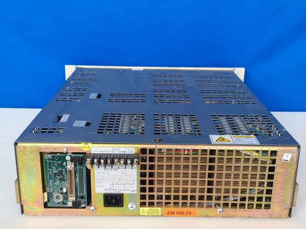
Input Voltage: 110/220 VAC ±10%, 50/60 Hz (auto-switching)
-
Protection: Overvoltage, overcurrent, short-circuit, thermal shutdown
-
User Port: 50-terminal rear panel (all controls, flags, programming signals accessible)
-
Remote Control: Analog voltage/current programming, GPIB (optional suffix -4886), RS-232
-
Operating Temperature: 0°C to +50°C (ambient, derate above 40°C)
-
Storage Temperature: -40°C to +85°C
-
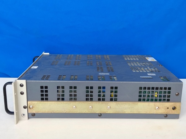
Physical: 19″ rackmount, 483 × 203 × 445 mm (W×H×D), 23 kg (50.7 lbs)
-
Cooling: Forced air (internal fans), side/rear ventilation required

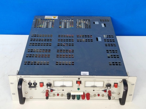
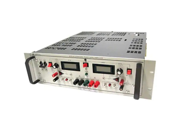
KEPCO BOP20-20M
The Real-World Problem It Solves
Testing motors, actuators, or magnetic components requires a power source that can not only drive current into a load but also absorb current back from it—something standard lab supplies can’t handle. The BOP20-20M eliminates the “one-quadrant limitation” headache by operating in all four quadrants: positive voltage/positive current (source), positive voltage/negative current (sink), negative voltage/positive current, and negative voltage/negative current. It handles the messy reality of back-EMF from motors, inductive kickback from coils, and capacitive loads without missing a beat, replicating arbitrary AC waveforms up to 4.6 kHz for dynamic simulation.
Where you’ll typically find it:
-
Motor test stands characterizing torque/speed curves and back-EMF behavior
-
Magnetic component testing (speakers, solenoids, transformers) with inductive loads up to 1 Henry
-
Servo system simulation and hardware-in-the-loop (HIL) testing
-
Particle accelerator magnet power supplies and medical imaging coil drivers
This amplifier keeps your test setup agile—no polarity switching relays, no external load banks for sinking, just seamless bipolar operation.
Hardware Architecture & Under-the-Hood Logic
The BOP20-20M isn’t a standard switching supply with a big output capacitor—it’s a linear power operational amplifier with active feedback control. The absence of energy-storage output capacitors allows the bandwidth and slew rate needed for waveform replication, but it also means the unit can’t ride through load transients like a conventional supply. The four-quadrant design uses complementary output stages that can source or sink current on demand, passing smoothly through zero volts without switching artifacts.
Internal Signal Flow:
-
Input Stage: External programming voltage (0-10V analog) or digital command (GPIB/RS-232) sets the output setpoint
-
Error Amplifier: High-speed analog comparator compares setpoint against actual output voltage/current feedback
-
Output Stage: Complementary bipolar transistor/FET output stage drives the load with up to ±20A; current sensing resistors provide feedback for current-mode operation
-
Four-Quadrant Bridge: Output configuration allows current flow in either direction regardless of voltage polarity, enabling motor braking and capacitive discharge
-
Protection Logic: Fast-acting electronic crowbars detect overvoltage/overcurrent conditions and clamp or shutdown within microseconds
-
Thermal Management: Forced-air cooling with internal temperature sensors; derating curve starts at 40°C ambient
KEPCO BOP20-20M
Field Service Pitfalls: What Rookies Get Wrong
Treating It Like a General-Purpose Lab Supply
The BOP20-20M is a high-speed power op-amp, not a bench supply. Engineers try to power up their 5V logic boards or LED arrays and wonder why the output overshoots, oscillates, or the unit faults on “overcurrent” during startup inrush.
-
Field Rule: This unit is for test and simulation of dynamic loads—motors, actuators, magnetic components. If you need a stable 24VDC bus for PLC I/O, use a standard KEPCO DPS series or similar. The BOP has no output capacitance to speak of; it can’t handle capacitive loads >0.1μF without external compensation. Check your load: if it’s mostly capacitive or needs hold-up during transients, this is the wrong tool.
Ignoring the Capacitive Load Stability Requirement
The BOP20-20M will oscillate with capacitive loads >0.1μF (long cables, filter capacitors, electronic loads). Rookies connect a motor drive input or a big electrolytic and the output starts singing at 50 kHz, sometimes damaging the load or the supply.
-
Quick Fix: For capacitive loads, you must slow the amplifier bandwidth using the feedback capacitance terminals on the 50-pin user port. Install an external capacitor (1nF to 100nF) between the designated pins (typically pins related to compensation) to roll off the response. Refer to the bandwidth correction table: with 100nF, the 4.6 kHz bandwidth drops to 500 Hz, but stability is restored. Start with 10nF and decrease if the response is too sluggish. Never exceed 0.1μF load capacitance without compensation.
Forgetting the “Source and Sink” Current Reality
The BOP can sink 20A just as easily as it sources 20A. In motor testing, this means regenerative energy from the motor’s back-EMF gets dumped back into the supply. Rookies set up a motor test stand, spin the motor up, then command a fast deceleration and watch the BOP fault on “overvoltage” because the motor became a generator and pumped energy back into the supply faster than it could dissipate.
-
Field Rule: When testing motors or inductive loads, ensure the BOP has a path to dissipate regenerated energy or use an external brake resistor/shunt regulator. The BOP will absorb the energy temporarily (it has some bus capacitance), but sustained sink current at high voltage will trip protections. Monitor the “Sink Current” flag on the user port during dynamic testing—if it’s active for more than a few milliseconds per cycle, you need an external dump circuit. For high-inertia loads, consider the inductive load variant (BOP20-20ML) with optimized current-mode stability.


