
Description
Detailed Parameter Table
| Parameter Name | Parameter Value |
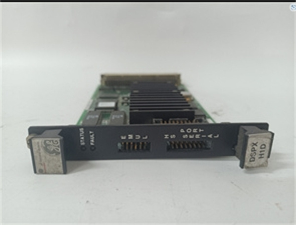
| Product model | IS200TRLYH1D |
| Manufacturer | General Electric (GE) Industrial Automation Division |
| Product category | Mid-Range Relay Output Terminal Board (Mark VI/Speedtronic Turbine Control System) |
| Core function | TMR contact voting, medium-current device control, enhanced surge protection, terminal connection |
| Relay configuration | 36 sealed electromechanical relays (3 TMR sections); 12 voted Form A (NO) outputs |
| Contact rating | 12 A per relay (resistive load); 6 A (inductive load); 24/125/250 V DC or 115/230 V AC |
| Input voltage | 24 V DC (coil drive); single power input with backup terminal |
| Terminal design | 48 screw terminals (torque range: 0.5–0.8 N·m); compatible with #12–22 AWG wires |
| Mounting type | DIN rail mounting (35 mm standard rails) |
| Protection features | Enhanced MOV surge suppression (1.2 kV clamping voltage); overcurrent fuses (5 A per TMR section) |
| Diagnostic capabilities | Coil drive current monitoring; TMR section fault indication (LEDs on-board) |
| Physical dimensions | 17.8 cm (W) × 33.0 cm (L) (7.0 in × 13.0 in) |
| Operating temperature range | -30 °C to 70 °C (-22 °F to 158 °F); derated to 60 °C at max current |
| Technology | Surface mount components; RoHS compliant |
| Compatibility | Mark VI/Vie systems; Class 1 Division 2 hazardous locations (limited) |
| Reference manual | GE Publication GEH-6721 C |
| Power distribution | Requires IS200WPDFH1B (single-power distribution board); no hot-swap support |
IS200DSPXH1D
Product Introduction
The IS200TRLYH1D is a mid-range relay output terminal board developed by GE for Mark VI/Speedtronic turbine control systems, bridging the gap between the entry-level IS200TRLYH1B and high-end IS200TRLYH3E. It retains the core TMR redundancy (3 sections, 12 voted outputs) that makes GE’s relay boards reliable, while upgrading key features like contact current rating (12 A vs. 10 A in 1B) and surge protection—making it ideal for medium-scale turbines (50–200 MW) where safety is critical but extreme capacity or diagnostics are unnecessary.
Unlike the basic IS200TRLYH1B, IS200TRLYH1D supports broader voltage compatibility (250 V DC/230 V AC vs. 125 V DC/115 V AC), enabling direct control of larger devices like 230 V AC lube oil pumps without external contactors. Its enhanced MOV surge suppression (1.2 kV clamping) also withstands higher voltage transients—common in grid-connected power plants or industrial facilities with unstable power.
In GE’s turbine control ecosystem, IS200TRLYH1D acts as a dependable “execution layer” for safety-critical actions. For example, when the Mark VI controller detects a bearing temperature spike, the board’s 3 TMR sections independently validate the “cooling fan start” command; only when all three sections agree does the voted output activate, ensuring the fan runs without false triggers. On-board LEDs simplify troubleshooting—each TMR section has a fault LED, allowing technicians to quickly identify failed sections without accessing the HMI.
Core Advantages and Technical Highlights
Balanced Current Capacity for Medium-Scale Needs: IS200TRLYH1D’s 12 A resistive load rating (2 A higher than the 1B model) strikes a balance between cost and performance. A 100 MW natural gas plant used it to control 12 devices: 6 fuel valves (24 V DC, 8 A), 4 cooling fans (230 V AC, 10 A), and 2 emergency solenoids (125 V DC, 3 A)—eliminating the need for external contactors (which added $2,000 per device in the 1B model). The 6 A inductive rating also supports small motors, avoiding the over-sizing required with the 1B’s 5 A limit.
Enhanced Surge Protection for Grid Stability: With a 1.2 kV clamping voltage MOV (vs. 1.0 kV in the 1B), IS200TRLYH1D better withstands voltage spikes from grid fluctuations or switching transients. A coal-fired power plant in India reported zero relay failures in 3 years of operation—compared to 2–3 annual failures with the IS200TRLYH1B—during monsoon season, when grid voltage often spiked to 1.1x nominal. The integrated 5 A fuses per TMR section also prevent damage from short circuits, a feature absent in the 1B model.
Simplified Troubleshooting with On-Board LEDs: IS200TRLYH1D adds LED indicators for each TMR section (green = normal, red = fault), a upgrade from the 1B’s single system LED. During a turbine outage at a waste-to-energy plant, technicians identified a failed TMR section in 5 minutes (via the red LED) vs. 30 minutes with the 1B (which required HMI access). This reduced maintenance time by 80% for routine fault checks, critical for plants with limited staff.
Broad Voltage Compatibility for Global Use: Unlike the IS200TRLYH1B (limited to 125 V DC/115 V AC), IS200TRLYH1D supports 250 V DC and 230 V AC—enabling deployment in European, Asian, and North American markets without region-specific variants. A multinational power company standardized on IS200TRLYH1D for its 150 MW turbines worldwide, reducing inventory costs by 40% (no need to stock 1B and 3E models for different regions).
Typical Application Scenarios
In a 150 MW combined-cycle plant’s gas turbine system, IS200TRLYH1D controls 12 critical devices: 4 natural gas control valves (24 V DC, 6 A), 3 exhaust temperature control dampers (230 V AC, 8 A), 3 lube oil pumps (250 V DC, 10 A), and 2 emergency shutdown solenoids (125 V DC, 4 A). Paired with the IS200WPDFH1B power board, its 3 TMR sections ensure reliable actuation. During a grid voltage dip, the enhanced MOV surge suppression clamped a 1.1 kV transient, protecting the relays from damage. On-board LEDs later alerted technicians to a weak TMR section (red LED), which was repaired during a scheduled shift—avoiding unplanned downtime.
In a pulp mill’s steam turbine system (120 MW), IS200TRLYH1D operates in a Class 1 Division 2 area, controlling 8 process valve solenoids (24 V DC, 5 A) and 4 condensate pump starters (230 V AC, 9 A). Its 12 A contact rating handles the pumps without external contactors, reducing cabinet size by 30% compared to the IS200TRLYH1B. The plant’s maintenance team values the screw terminals—they provide a secure connection in the mill’s dusty environment, with no loose wires reported in 2 years of operation.
In a remote diesel-fired power plant (80 MW), IS200TRLYH1D controls the turbine’s fuel injection valves (24 V DC, 7 A) and cooling system fans (115 V AC, 8 A). Its single power input with backup terminal ensures operation during generator load swings—if the main 24 V DC supply drops, the backup terminal (connected to a battery) maintains coil power. Coil current monitoring also detected a failing fuel valve relay (current dropping from 100 mA to 60 mA), allowing replacement before it failed during peak demand.
Related Model Recommendations
IS200WPDFH1B: GE’s single-power distribution board, mandatory for IS200TRLYH1D. Provides 24 V DC input and 5 A fuses per TMR section—matching the board’s protection needs.
IS200TRLYH1B: Entry-level predecessor to IS200TRLYH1D, with 10 A contacts and basic surge protection. Cost-effective for small turbines (<50 MW) with low-current devices.
IS200TRLYH3E: Advanced successor, with 4 TMR sections, 15 A contacts, and predictive diagnostics. Upgrade option for large turbines (>200 MW) needing maximum redundancy.
IS200TFBAH1A: GE’s Mark VI CPU module. Issues control commands to IS200TRLYH1D and monitors coil current via the backplane.
IS200EHBQG2A: GE’s standard backplane module. Enables communication between IS200TRLYH1D and the CPU, supporting fault data transmission.
IS200JGNDG1A: GE’s grounding module. Enhances IS200TRLYH1D’s surge suppression by providing a low-impedance ground path for MOVs.
GE CR4800 Relay: Replacement relay for IS200TRLYH1D. Matches the board’s 12 A rating and socket design; RoHS compliant.
IS200TBCIH2C: GE’s contact input terminal board. Complements IS200TRLYH1D by providing feedback from field devices (e.g., valve position switches) to the CPU.
IS200DSPXH1D
Installation, Commissioning and Maintenance Instructions
Installation preparation: Before installing IS200TRLYH1D, power off the Mark VI cabinet and use ESD-safe tools. Mount the board on a 35 mm DIN rail, ensuring 10 cm clearance above/below for heat (derate to 60 °C at 12 A). Connect the 24 V DC power input to IS200WPDFH1B, and attach the backup terminal to a 24 V DC battery (optional). For wiring: Use screw terminals—strip wires to 6 mm, tighten to 0.5–0.8 N·m, and label each output (e.g., “Fuel Valve 2 Output”). Verify wire gauge compatibility (#12 AWG for 12 A loads, #22 AWG for low-current devices).
Commissioning & configuration: Use GE’s ToolboxST software (GEH-6721 C) to set TMR voting logic (2-out-of-3). Calibrate coil current thresholds (90–110 mA for healthy relays). Test each output by issuing commands from the Mark VI HMI—confirm the voted output activates only when all 3 TMR relays close, and check on-board LEDs (green = normal, red = fault).
Maintenance suggestions: Inspect terminals quarterly—tighten loose screws and clean debris with a dry brush. Test relay contacts annually with a multimeter (replace if resistance >1 Ω). Monitor coil current via the CPU—alert if current drops below 80 mA or rises above 120 mA. If a TMR section faults (red LED), power off the board, replace the affected relays (GE CR4800), and reset the fuse. Never use non-GE relays—they may not fit the socket or meet current ratings.
Service and Guarantee Commitment
IS200TRLYH1D comes with a 4-year standard warranty from GE, covering defects in materials (relays, MOVs) and workmanship. If the board fails within this period (e.g., TMR section fault, surge suppression failure), GE will ship a replacement within 24 hours from regional warehouses (North America, Europe, Asia) and provide free technical support for reinstallation.
GE offers 24/7 global support for IS200TRLYH1D: Certified Mark VI engineers assist with TMR configuration, surge protection testing, and troubleshooting via phone, email, or remote access. Customers gain access to GEH-6721 C, relay replacement guides, and compatibility matrices. For semi-critical systems (e.g., industrial turbines, small power plants), GE provides extended warranties (up to 6 years) and bi-annual remote diagnostics checks—ensuring compliance with IEC 61010 standards and 99.99% operational reliability.


